Infiniti I35 (A33). Manual — part 213
7
CHECK MAF SENSOR INPUT SIGNAL CIRCUIT FOR OPEN AND SHORT
1. Check harness continuity between MAF sensor terminal 1 and ECM terminal 62.
Refer to Wiring Diagram.
Continuity should exist.
2. Also check harness for short to ground and short to power.
OK or NG
OK
©
GO TO 8.
NG
©
Repair open circuit or short to ground or short to power in harness or connectors.
8
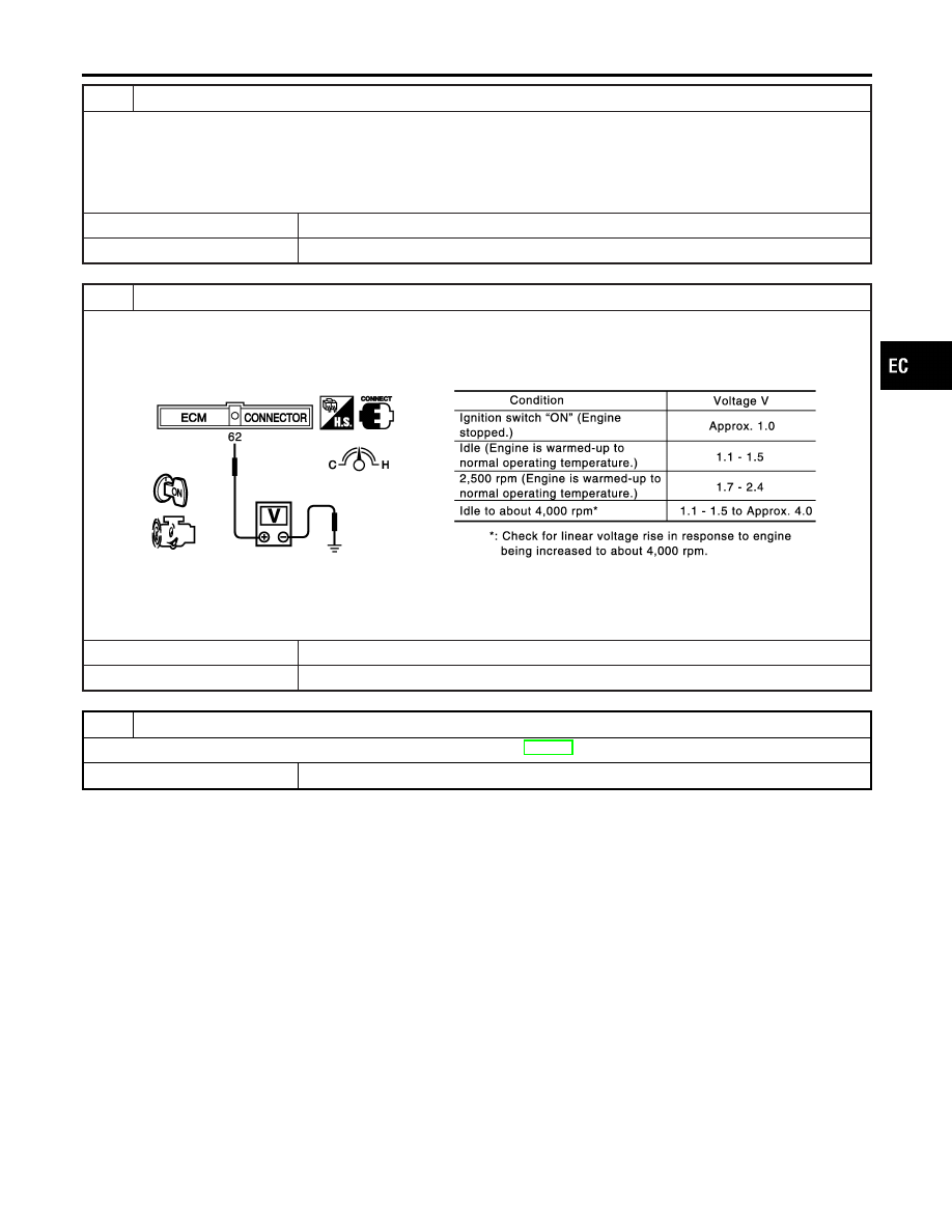
CHECK MASS AIR FLOW SENSOR
1. Reconnect harness connectors disconnected.
2. Start engine and warm it up to normal operating temperature.
3. Check voltage between ECM terminal 62 (Mass air flow sensor signal) and ground.
SEC103D
4. If the voltage is out of specification, disconnect MAF sensor harness connector and connect it again.
Then repeat above check.
OK or NG
OK
©
GO TO 9.
NG
©
Replace mass air flow sensor.
9
CHECK INTERMITTENT INCIDENT
Refer to “TROUBLE DIAGNOSIS FOR INTERMITTENT INCIDENT”, EC-152.
©
INSPECTION END
GI
MA
EM
LC
FE
AT
AX
SU
BR
ST
RS
BT
HA
SC
EL
IDX
DTC P0101 MAF SENSOR
Diagnostic Procedure (Cont’d)
EC-193
SEC266C
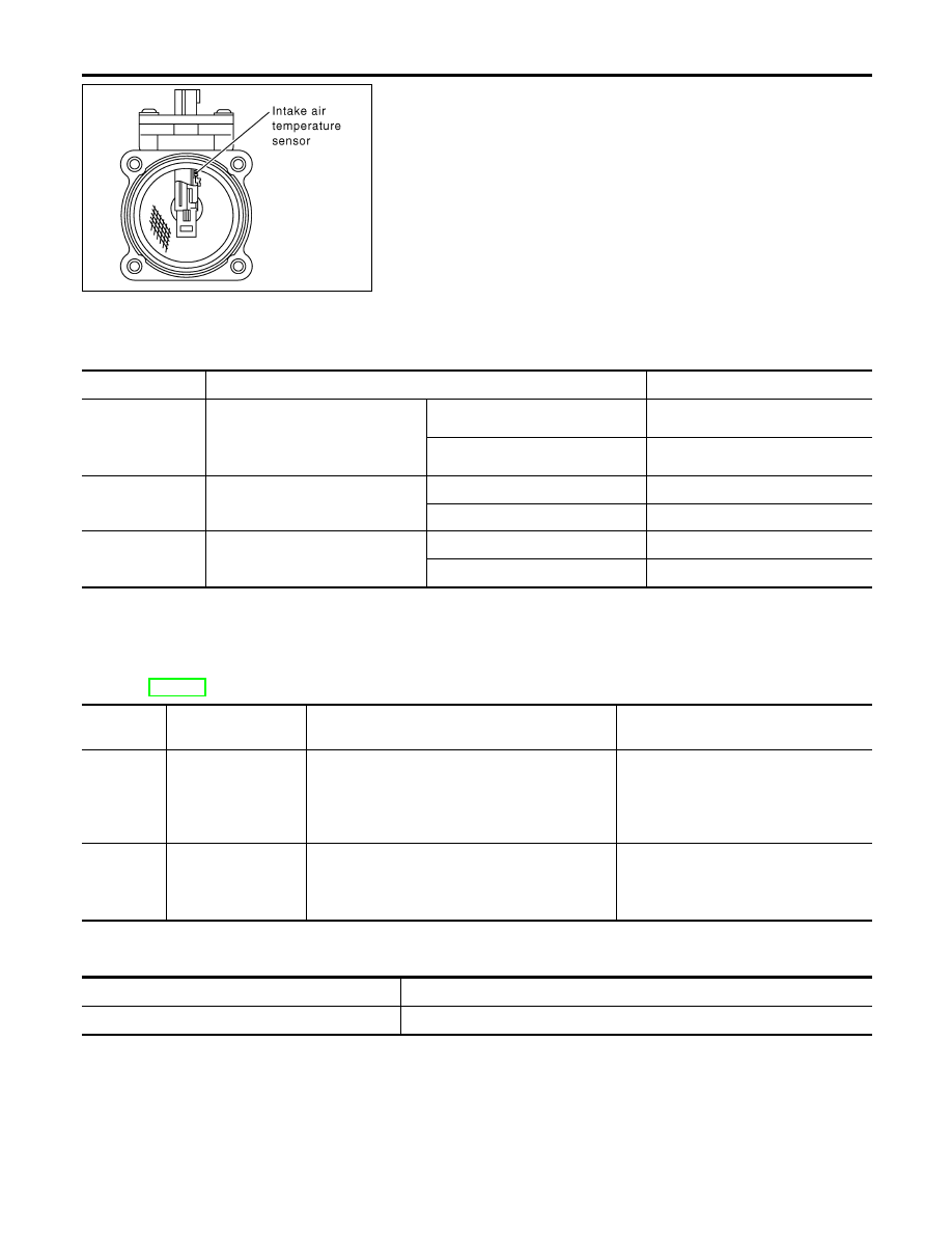
Component Description
NHEC0746
The mass air flow sensor is placed in the stream of intake air. It
measures the intake flow rate by measuring a part of the entire
intake flow. It consists of a hot film that is supplied with electric
current from the ECM. The temperature of the hot film is controlled
by the ECM a certain amount. The heat generated by the hot film
is reduced as the intake air flows around it. The more air, the
greater the heat loss.
Therefore, the ECM must supply more electric current to maintain
the temperature of the hot film as air flow increases. The ECM
detects the air flow by means of this current change.
CONSULT-II Reference Value in Data Monitor
Mode
NHEC0747
Specification data are reference values.
MONITOR ITEM
CONDITION
SPECIFICATION
MAS A/F SE-B1
I
Engine: After warming up
I
Air conditioner switch: OFF
I
Shift lever: N
I
No-load
Idle
1.1 - 1.5V
2,500 rpm
1.7 - 2.4V
CAL/LD VALUE
ditto
Idle
10 - 35%
2,500 rpm
10 - 35%
MASS AIRFLOW
ditto
Idle
2.0 - 6.0 g·m/s
2,500 rpm
7.0 - 20.0 g·m/s
On Board Diagnosis Logic
NHEC1429
These self-diagnoses have the one trip detection logic.
NOTE:
If DTC P0102 or P0103 is displayed with DTC P1229, first perform the trouble diagnosis for DTC P1229.
Refer to EC-539.
DTC No.
Trouble diagnosis
name
DTC Detecting Condition
Possible Cause
P0102
0102
Mass air flow sensor
circuit low input
An excessively low voltage from the sensor is sent
to ECM when engine is running.
I
Harness or connectors
(The sensor circuit is open or
shorted.)
I
Intake air leaks
I
Mass air flow sensor
P0103
0103
Mass air flow sensor
circuit high input
An excessively high voltage from the sensor is
sent to ECM.
I
Harness or connectors
(The sensor circuit is open or
shorted.)
I
Mass air flow sensor
FAIL-SAFE MODE
NHEC1429S01
When the malfunction is detected, the ECM enters fail-safe mode and the MIL lights up.
Detected items
Engine operating condition in fail-safe mode
Mass air flow sensor circuit
Engine speed will not rise more than 2,400 rpm due to the fuel cut.
DTC P0102, P0103 MAF SENSOR
Component Description
EC-194
DTC Confirmation Procedure
NHEC1430
NOTE:
If DTC Confirmation Procedure has been previously conducted,
always turn ignition switch OFF and wait at least 10 seconds before
conducting the next test.
SEF058Y
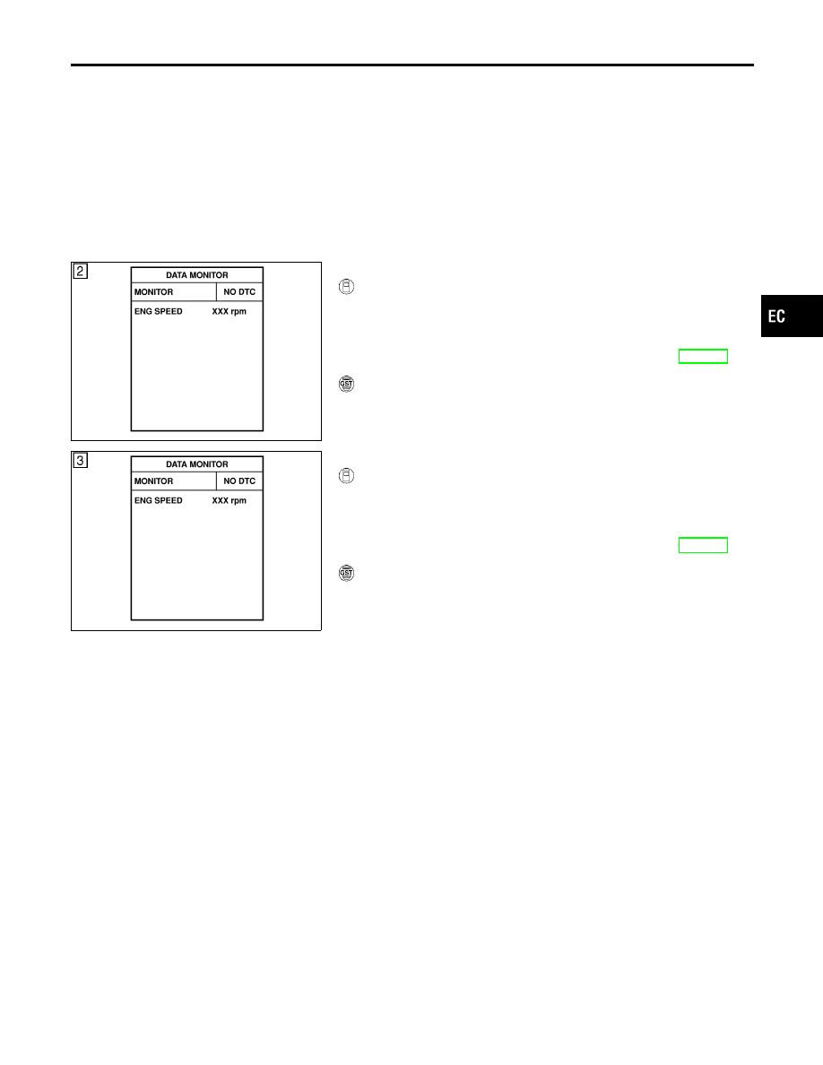
PROCEDURE FOR DTC P0103
NHEC1430S01
With CONSULT-II
NHEC1430S0101
1)
Turn ignition switch ON.
2)
Select “DATA MONITOR” mode with CONSULT-II.
3)
Wait at least 6 seconds.
4)
If DTC is detected, go to “Diagnostic Procedure”, EC-197.
With GST
NHEC1430S0102
Follow the procedure “With CONSULT-II” above.
SEF058Y
PROCEDURE FOR DTC P0102
NHEC1430S02
With CONSULT-II
NHEC1430S0201
1)
Turn ignition switch ON.
2)
Select “DATA MONITOR” mode with CONSULT-II.
3)
Start engine and wait at least 5 seconds.
4)
If DTC is detected, go to “Diagnostic Procedure”, EC-197.
With GST
NHEC1430S0202
Follow the procedure “With CONSULT-II” above.
GI
MA
EM
LC
FE
AT
AX
SU
BR
ST
RS
BT
HA
SC
EL
IDX
DTC P0102, P0103 MAF SENSOR
DTC Confirmation Procedure
EC-195
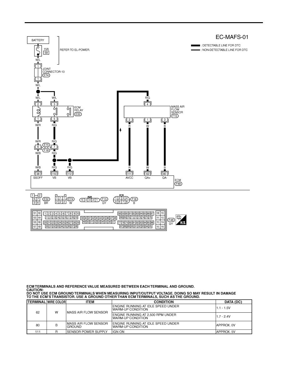
Wiring Diagram
NHEC0753
MEC531D
SEF650XE
DTC P0102, P0103 MAF SENSOR
Wiring Diagram
EC-196
Нет комментариевНе стесняйтесь поделиться с нами вашим ценным мнением.
Текст