Infiniti I35 (A33). Manual — part 320
Wiring Diagram
NHEC1221
MEC367E
GI
MA
EM
LC
FE
AT
AX
SU
BR
ST
RS
BT
HA
SC
EL
IDX
DTC P1572 ASCD BRAKE SWITCH
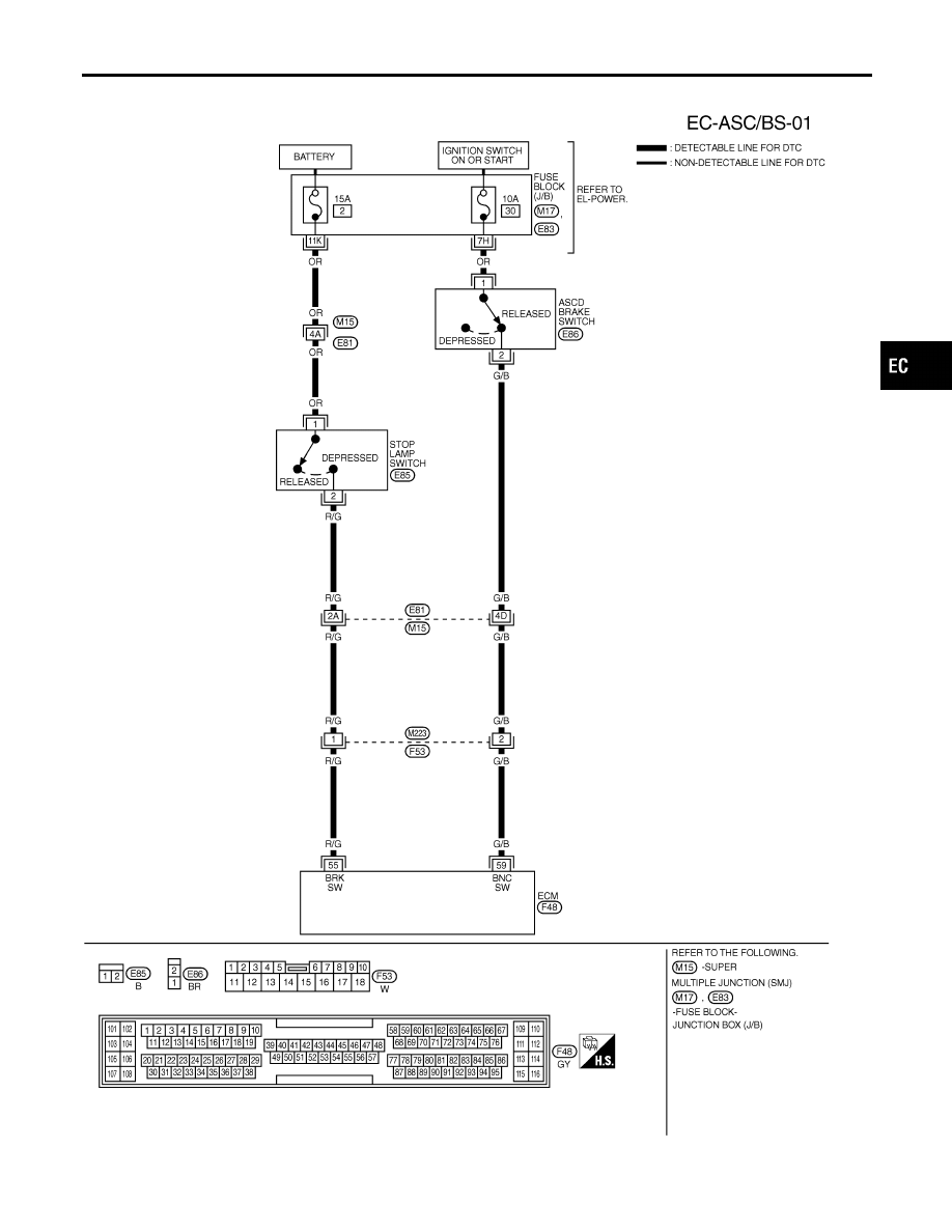
Wiring Diagram
EC-621

Specification data are reference values and are measured between each terminal and ground.
CAUTION:
Do not use ECM ground terminals when measuring input/output voltage. Doing so may result in dam-
age to the ECM’s transistor. Use a ground other than ECM terminals, such as the ground.
TERMI-
NAL
NO.
WIRE
COLOR
ITEM
CONDITION
DATA (DC Voltage)
55
R/G
Stop lamp switch
[Ignition switch ON]
I
Brake pedal is released
Approximately 0V
[Ignition switch ON]
I
Brake pedal is depressed
BATTERY VOLTAGE
(11 - 14V)
59
G/B
ASCD brake switch
[Ignition switch ON]
I
Brake pedal is released
BATTERY VOLTAGE
(11 - 14V)
[Ignition switch ON]
I
Brake pedal is depressed
Approximately 0V
DTC P1572 ASCD BRAKE SWITCH
Wiring Diagram (Cont’d)
EC-622
Diagnostic Procedure
NHEC1222
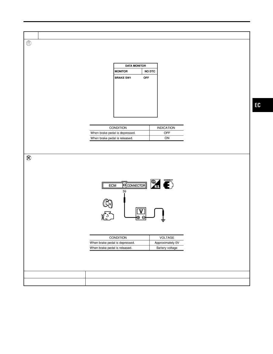
1
CHECK OVERALL FUNCTION-I
With CONSULT-II
1. Turn ignition switch ON.
2. Select “BRAKE SW1” in “DATA MONITOR” mode with CONSULT-II.
3. Check the indication of “BRAKE SW1” under the following conditions.
SEC011D
MTBL1557
Without CONSULT-II
1. Turn ignition switch ON.
2. Check voltage between ECM terminal 59 and ground under the following conditions.
SEC012D
MTBL1558
Refer to Wiring Diagram.
OK or NG
OK
©
GO TO 2.
NG
©
GO TO 3.
GI
MA
EM
LC
FE
AT
AX
SU
BR
ST
RS
BT
HA
SC
EL
IDX
DTC P1572 ASCD BRAKE SWITCH
Diagnostic Procedure
EC-623
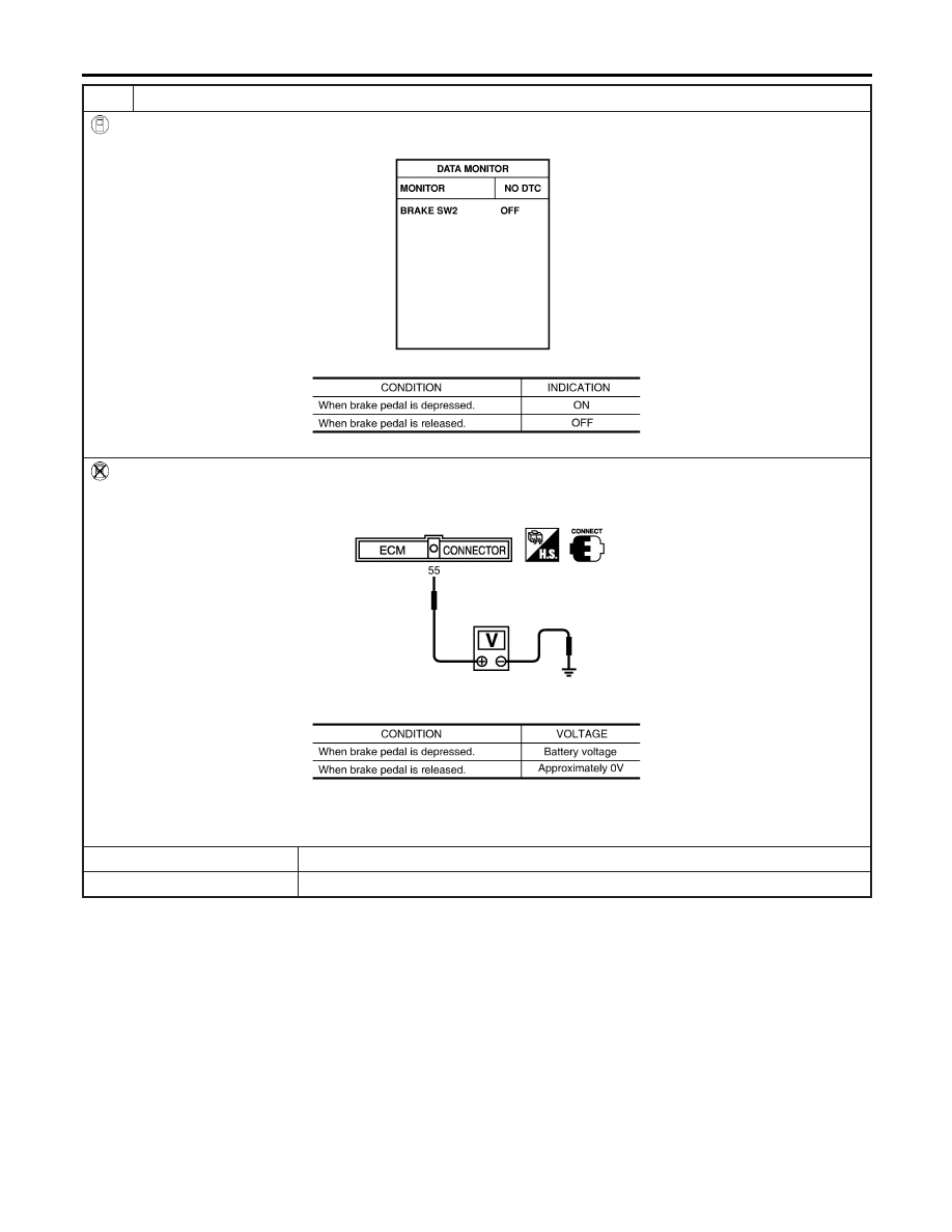
2
CHECK OVERALL FUNCTION-II
With CONSULT-II
See “BRAKE SW2” indication in “DATA MONITOR” mode.
SEC013D
MTBL1336
Without CONSULT-II
Check voltage between ECM terminal 55 and ground under the following conditions.
SEC014D
MTBL1337
Refer to Wiring Diagram.
OK or NG
OK
©
GO TO 14.
NG
©
GO TO 9.
DTC P1572 ASCD BRAKE SWITCH
Diagnostic Procedure (Cont’d)
EC-624
Нет комментариевНе стесняйтесь поделиться с нами вашим ценным мнением.
Текст