Infiniti I35 (A33). Manual — part 321
3
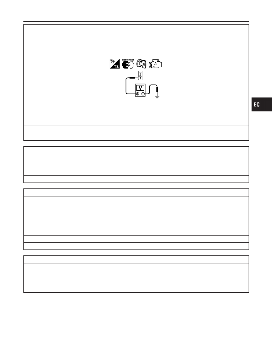
CHECK ASCD BRAKE SWITCH POWER SUPPLY CIRCUIT
1. Turn ignition switch OFF.
2. Disconnect ASCD brake switch harness connector.
3. Turn ignition switch ON.
4. Check voltage between ASCD brake switch terminal 1 and ground with CONSULT-II or tester.
PBIB0857E
Voltage: Battery voltage
OK or NG
OK
©
GO TO 5.
NG
©
GO TO 4.
4
DETECT MALFUNCTIONING PART
Check the following.
I
Fuse block (J/B) connector E83
I
10A fuse
I
Harness for open or short between ASCD brake switch and fuse
©
Repair open circuit or short to ground or short to power in harness or connectors.
5
CHECK ASCD BRAKE SWITCH INPUT CIRCUIT FOR OPEN AND SHORT
1. Turn ignition switch OFF.
2. Disconnect ECM harness connector.
3. Check harness continuity between ECM terminal 59 and ASCD brake switch terminal 2.
Refer to Wiring Diagram.
Continuity should exist.
4. Also check harness for open to ground and short to power.
OK or NG
OK
©
GO TO 9.
NG
©
GO TO 6.
6
DETECT MALFUNCTIONING PART
Check the following.
I
Harness connectors E81, M15
I
Harness connectors M223, F53
I
Harness for open and short between ECM and ASCD brake switch
©
Repair open circuit or short to ground or short to power in harness or connectors.
GI
MA
EM
LC
FE
AT
AX
SU
BR
ST
RS
BT
HA
SC
EL
IDX
DTC P1572 ASCD BRAKE SWITCH
Diagnostic Procedure (Cont’d)
EC-625
7
CHECK ASCD BRAKE SWITCH
Refer to “Component Inspection”, EC-628.
OK or NG
OK
©
GO TO 8.
NG
©
Replace ASCD brake switch.
8
DETECT MALFUNCTIONING PART
Check the following.
I
Harness connectors E81, M15
I
Harness connectors M223, F53
©
Repair open circuit or short to ground or short to power in harness or connectors.
9
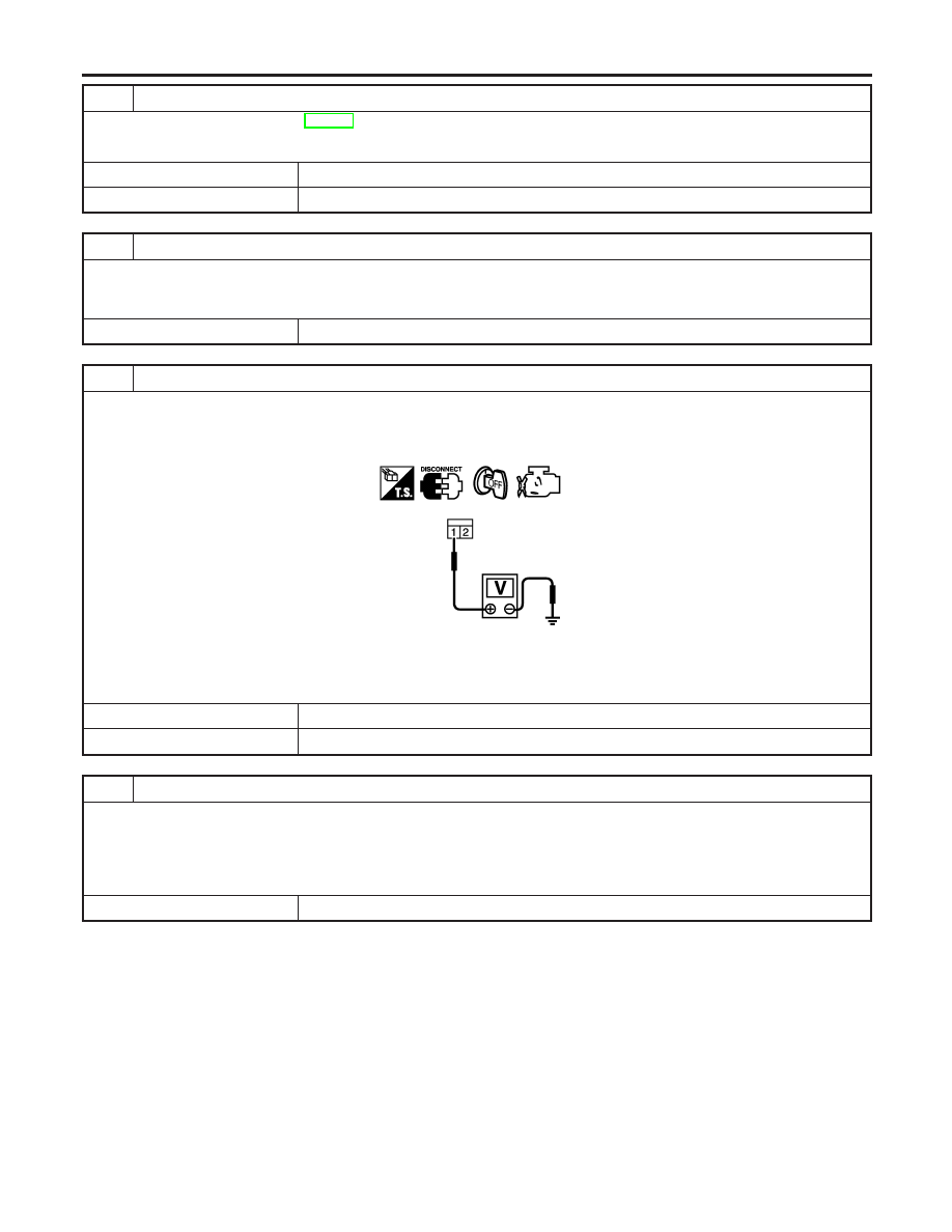
CHECK STOP LAMP SWITCH POWER SUPPLY CIRCUIT
1. Turn ignition switch OFF.
2. Disconnect stop lamp switch harness connector.
3. Check voltage between stop lamp switch terminal 1 and ground with CONSULT-II or tester.
PBIB0117E
Voltage: Battery voltage
OK or NG
OK
©
GO TO 12.
NG
©
GO TO 11.
10
DETECT MALFUNCTIONING PART
Check the following.
I
Fuse block (J/B) connector M17
I
15A fuse
I
Harness connectors M15, E81
I
Harness for open or short between stop lamp switch and fuse
©
Repair open circuit or short to ground in harness or connectors.
DTC P1572 ASCD BRAKE SWITCH
Diagnostic Procedure (Cont’d)
EC-626
11
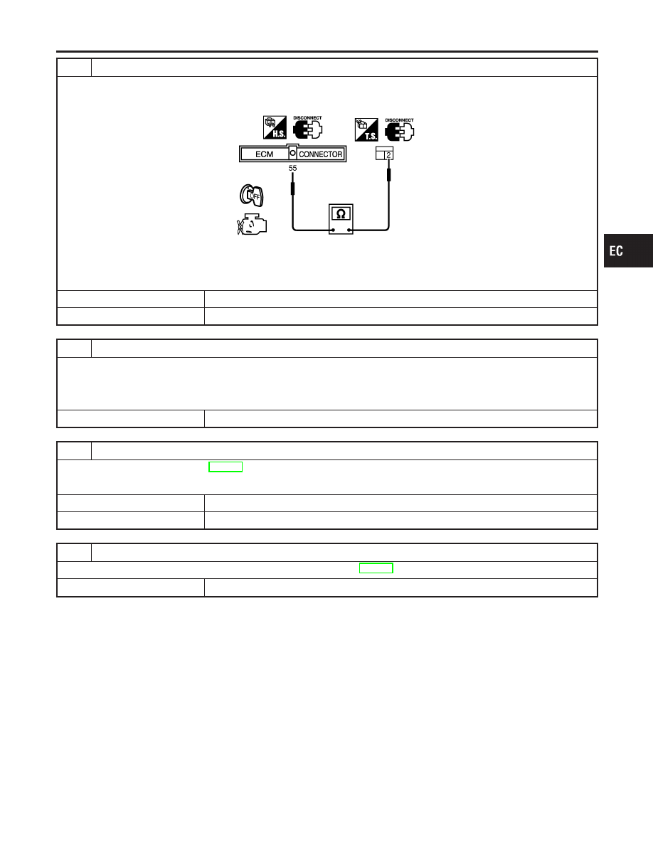
CHECK STOP LAMP SWITCH INPUT SIGNAL CIRCUIT FOR OPEN AND SHORT
1. Disconnect ECM harness connector.
2. Check harness continuity between stop lamp switch terminal 2 and ECM terminal 55.
SEC216D
Continuity should exist
3. Also check harness for short to ground and short to power.
OK or NG
OK
©
GO TO 13.
NG
©
GO TO 12.
12
DETECT MALFUNCTIONING PART
Check the following.
I
Harness connectors M15, E81
I
Harness connectors M223, F53
I
Harness for open or short between stop lamp switch and ECM
©
Repair open circuit or short to ground or short to power in harness or connectors.
13
CHECK STOP LAMP SWITCH
Refer to “Component Inspection”, EC-628.
OK or NG
OK
©
GO TO 14.
NG
©
Replace stop lamp switch.
14
CHECK INTERMITTENT INCIDENT
Refer to “TROUBLE DIAGNOSIS FOR INTERMITTENT INCIDENT”, EC-152.
©
INSPECTION END
GI
MA
EM
LC
FE
AT
AX
SU
BR
ST
RS
BT
HA
SC
EL
IDX
DTC P1572 ASCD BRAKE SWITCH
Diagnostic Procedure (Cont’d)
EC-627
SEC023D
SEC155D
Component Inspection
NHEC1223
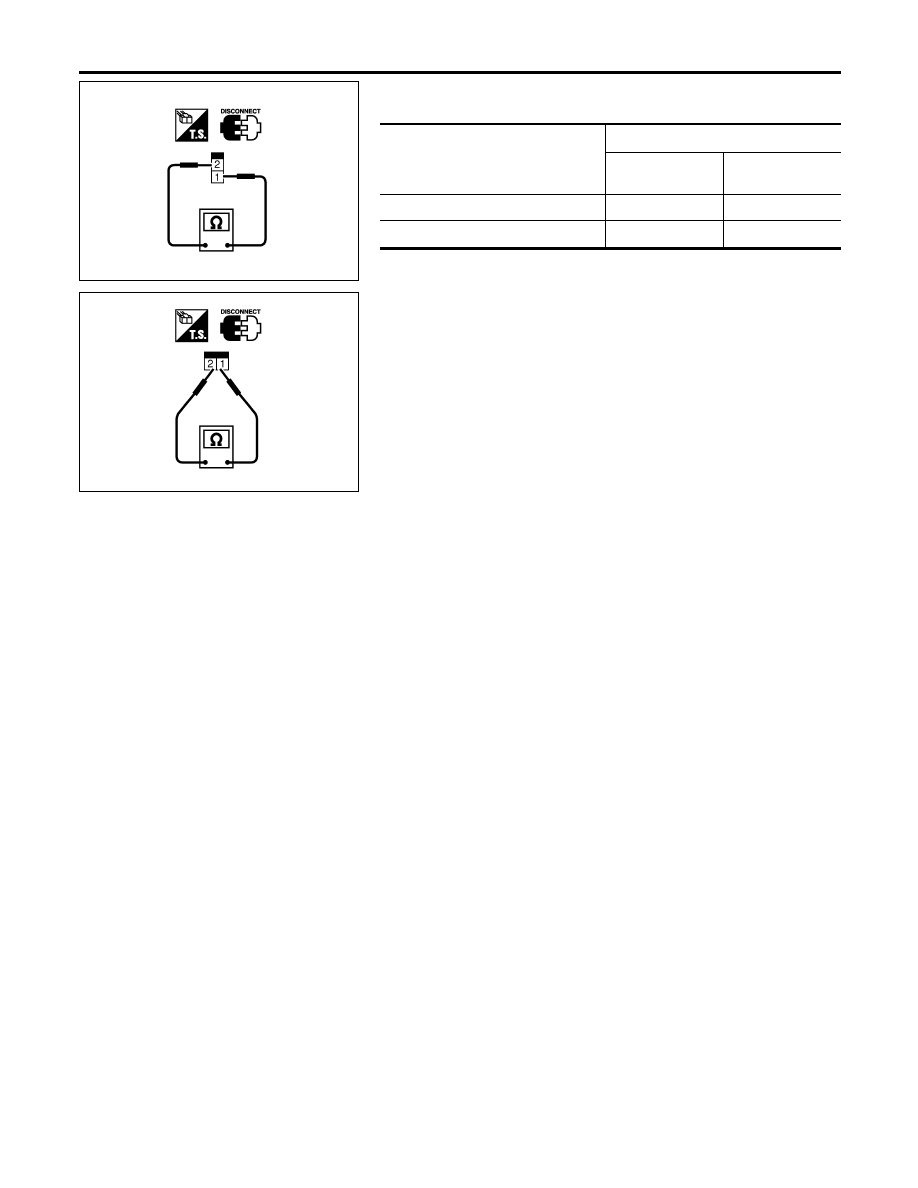
ASCD BRAKE SWITCH AND STOP LAMP SWITCH
Condition
Continuity
ASCD brake
switch
Stop lamp switch
When brake pedal is depressed
No
Yes
When brake pedal is released
Yes
No
Check each switch after adjusting brake pedal — refer to BR
section.
DTC P1572 ASCD BRAKE SWITCH
Component Inspection
EC-628
Нет комментариевНе стесняйтесь поделиться с нами вашим ценным мнением.
Текст