Infiniti I35 (A33). Manual — part 318

DTC Confirmation Procedure
NHEC1463
NOTE:
If DTC Confirmation Procedure has been previously conducted,
always turn ignition switch OFF and wait at least 10 seconds before
conducting the next test.
With CONSULT-II
1.
Turn ignition switch ON.
2.
Select “DATA MONITOR” mode with CONSULT-II.
3.
Wait at least 10 seconds.
4.
Press MAIN switch for at least 10 seconds, then release it and
wait at least 10 seconds.
5.
Press RESUME/ACCEL switch for at least 10 seconds, then
release it and wait at least 10 seconds.
6.
Press SET/COAST switch for at least 10 seconds, then
release it and wait at least 10 seconds.
7.
Press CANCEL switch for at least 10 seconds, then release it
and wait at least 10 seconds.
8.
If 1st trip DTC is detected, go to “Diagnostic Procedure”,
EC-615.
With GST
Follow the procedure “With CONSULT-II” above.
GI
MA
EM
LC
FE
AT
AX
SU
BR
ST
RS
BT
HA
SC
EL
IDX
DTC P1564 ASCD STEERING SWITCH
DTC Confirmation Procedure
EC-613

Wiring Diagram
NHEC1464
MEC643E
DTC P1564 ASCD STEERING SWITCH
Wiring Diagram
EC-614
Specification data are reference values and are measured between each terminal and ground.
CAUTION:
Do not use ECM ground terminals when measuring input/output voltage. Doing so may result in dam-
age to the ECM’s transistor. Use a ground other than ECM terminals, such as the ground.
TERMI-
NAL
NO.
WIRE
COLOR
ITEM
CONDITION
DATA (DC Voltage)
50
G/Y
ASCD steering switch
[Ignition switch ON]
I
ASCD steering switch is OFF.
Approximately 4.0V
[Ignition switch ON]
I
MAIN switch: Pressed
Approximately 0V
[Ignition switch ON]
I
CANCEL switch: Pressed
Approximately 1V
[Ignition switch ON]
I
SET/COAST switch: Pressed
Approximately 2V
[Ignition switch ON]
I
RESUME/ACCEL switch: Pressed
Approximately 3V
58
B
Sensor ground
[Engine is running]
I
Warm-up condition
I
Idle speed
Approximately 0V
Diagnostic Procedure
NHEC1465
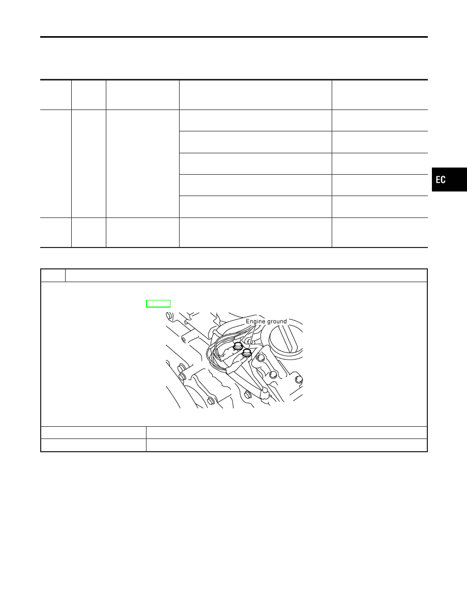
1
CHECK GROUND CONNECTIONS
1. Turn ignition switch OFF.
2. Loosen and retighten two engine ground screws.
Refer to “Ground Inspection”, EC-160.
SEC047D
OK or NG
OK
©
GO TO 2.
NG
©
Repair or replace ground connections.
GI
MA
EM
LC
FE
AT
AX
SU
BR
ST
RS
BT
HA
SC
EL
IDX
DTC P1564 ASCD STEERING SWITCH
Wiring Diagram (Cont’d)
EC-615

2
CHECK ASCD STEERING SWITCH CIRCUIT
With CONSULT-II
1. Turn ignition switch ON.
2. Select “MAIN SW”, “RESUME/ACC SW”, “SET SW” and “CANCEL SW” in “DATA MONITOR” mode with CONSULT-II.
SEC006D
3. Check each item indication under the following conditions.
MTBL1841
Without CONSULT-II
1. Turn ignition switch ON.
2. Check voltage between ECM terminal 50 and ground with pressing each button.
SEC007D
MTBL1842
Refer to Wiring Diagram.
OK or NG
OK
©
GO TO 5.
NG
©
GO TO 3.
DTC P1564 ASCD STEERING SWITCH
Diagnostic Procedure (Cont’d)
EC-616
Нет комментариевНе стесняйтесь поделиться с нами вашим ценным мнением.
Текст