Infiniti I35 (A33). Manual — part 244
SEF058Y
DTC Confirmation Procedure
=NHEC0942
NOTE:
If DTC Confirmation Procedure has been previously conducted,
always turn ignition switch OFF and wait at least 10 seconds before
conducting the next test.
TESTING CONDITION:
Before performing the following procedure, confirm that bat-
tery voltage is more than 10.5V with ignition switch ON.
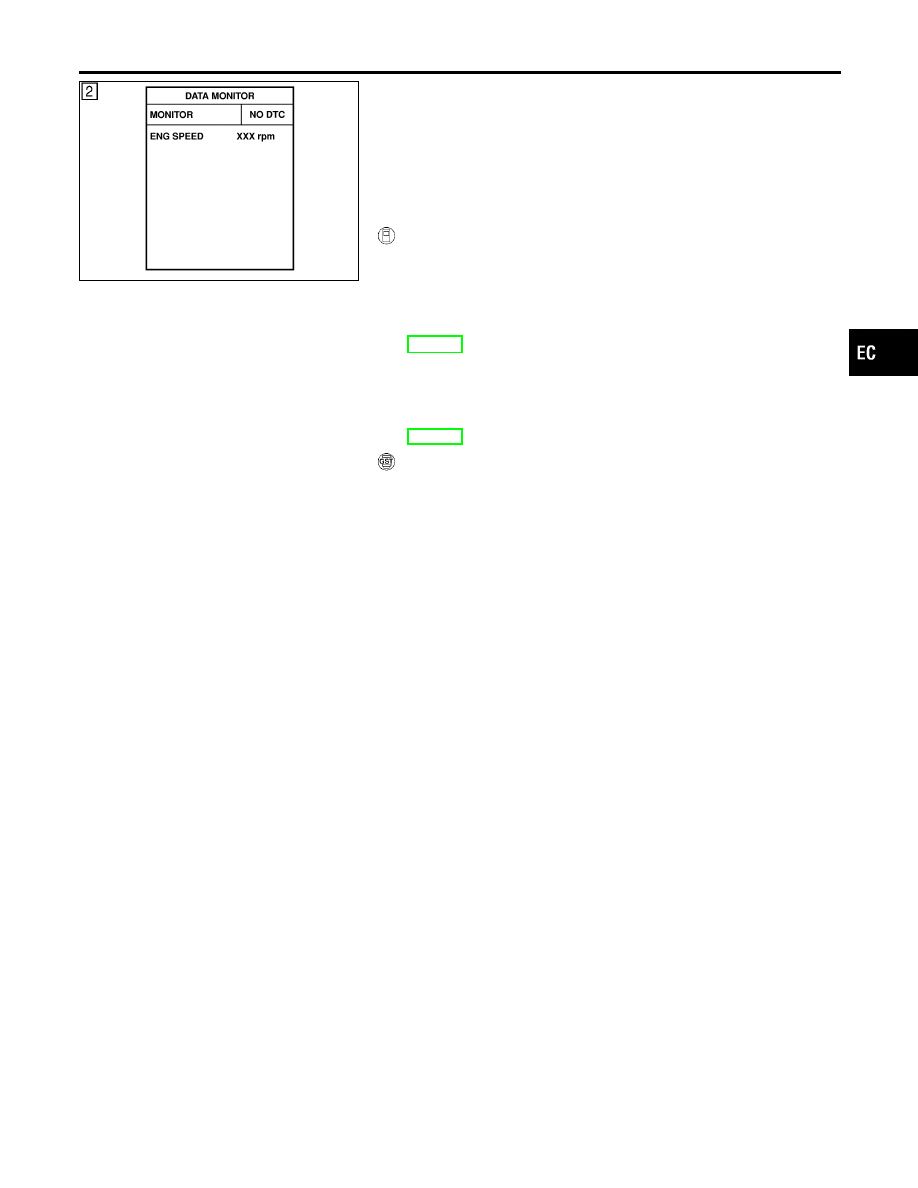
With CONSULT-II
1)
Turn ignition switch ON and select “DATA MONITOR” mode
with CONSULT-II.
2)
Crank engine for at least 2 seconds and run it for at least 5
seconds at idle speed.
3)
If 1st trip DTC is detected, go to “Diagnostic Procedure”,
EC-319.
If 1st trip DTC is not detected, go to next step.
4)
Maintaining engine speed at more than 1,000 rpm for at least
5 seconds.
5)
If 1st trip DTC is detected, go to “Diagnostic Procedure”,
EC-319
With GST
Follow the procedure “With CONSULT-II” above.
GI
MA
EM
LC
FE
AT
AX
SU
BR
ST
RS
BT
HA
SC
EL
IDX
DTC P0335 CKP SENSOR (POS)
DTC Confirmation Procedure
EC-317
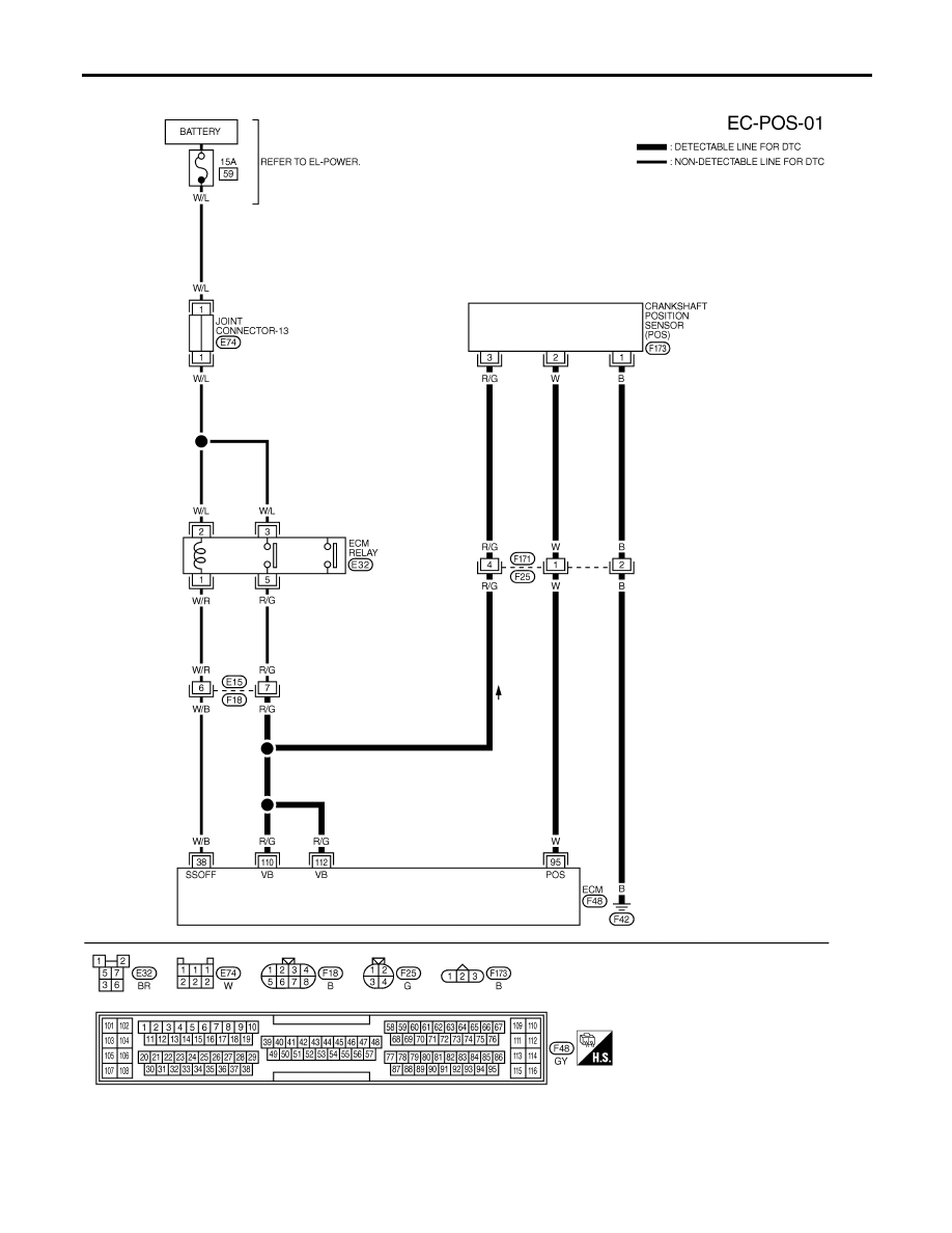
Wiring Diagram
NHEC0943
MEC551D
DTC P0335 CKP SENSOR (POS)
Wiring Diagram
EC-318
Specification data are reference values and are measured between each terminal and ground.
CAUTION:
Do not use ECM ground terminals when measuring input/output voltage. Doing so may result in dam-
age to the ECM’s transistor. Use a ground other than ECM terminals, such as the ground.
TERMI-
NAL
NO.
WIRE
COLOR
ITEM
CONDITION
DATA (DC Voltage)
95
W
Crankshaft position
sensor (POS)
[Engine is running]
I
Idle speed
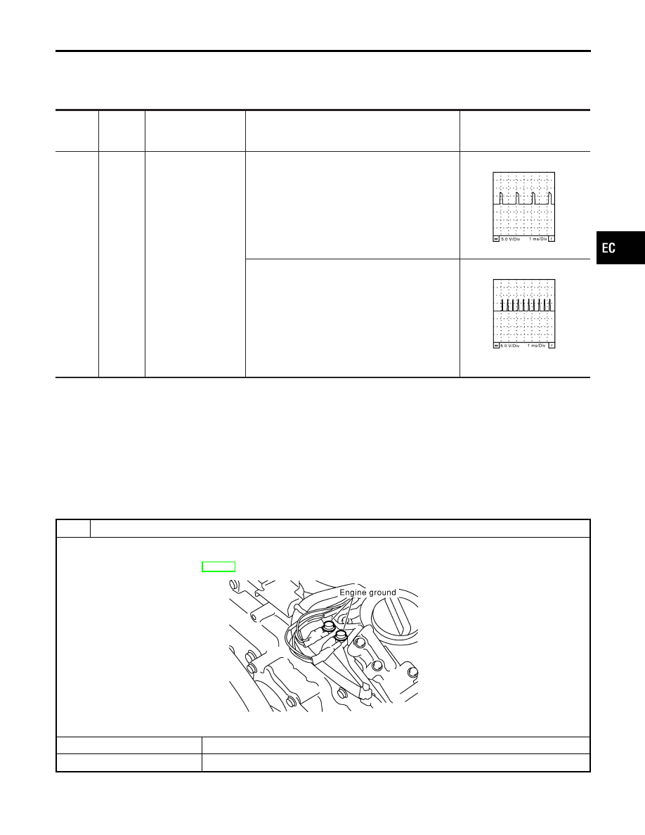
NOTE:
The pulse cycle changes depending on rpm at idle.
Approximately 2.4V
★
SEC035D
[Engine is running]
I
Engine speed is 2,000 rpm.
Approximately 2.3V
★
SEC036D
★
: Average voltage for pulse signal (Actual pulse signal can be confirmed by oscilloscope.)
Diagnostic Procedure
NHEC0944
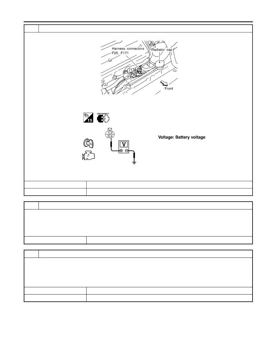
1
CHECK GROUND CONNECTIONS
1. Turn ignition switch OFF.
2. Loosen and retighten two engine ground screws.
Refer to “Ground Inspection”, EC-160.
SEC047D
OK or NG
OK
©
GO TO 2.
NG
©
Repair or replace ground connections.
GI
MA
EM
LC
FE
AT
AX
SU
BR
ST
RS
BT
HA
SC
EL
IDX
DTC P0335 CKP SENSOR (POS)
Wiring Diagram (Cont’d)
EC-319
2
CHECK CKP SENSOR (POS) POWER SUPPLY CIRCUIT
1. Disconnect harness connectors F25, F171.
SEF511WB
2. Turn ignition switch ON.
3. Check voltage between harness connector F25 terminal 4 and ground with CONSULT-II or tester.
SEF323X
4. Also check harness for short to ground and short to power.
OK or NG
OK
©
GO TO 4.
NG
©
GO TO 3.
3
DETECT MALFUNCTIONING PART
Check the following.
I
Harness connectors F25, F171
I
Harness connectors E15, F18
I
Harness for open or short between ECM and harness connector F25
I
Harness for open or short between ECM relay and harness connector F25
©
Repair open circuit or short to ground or short to power in harness or connectors.
4
CHECK CKP SENSOR (POS) GROUND CIRCUIT FOR OPEN AND SHORT
1. Turn ignition switch OFF.
2. Check harness continuity between harness connector F25 terminal 2 and ground. Refer to Wiring Diagram.
Continuity should exist.
3. Also check harness for short to power.
OK or NG
OK
©
GO TO 6.
NG
©
GO TO 5.
DTC P0335 CKP SENSOR (POS)
Diagnostic Procedure (Cont’d)
EC-320
Нет комментариевНе стесняйтесь поделиться с нами вашим ценным мнением.
Текст