Infiniti I35 (A33). Manual — part 242
11
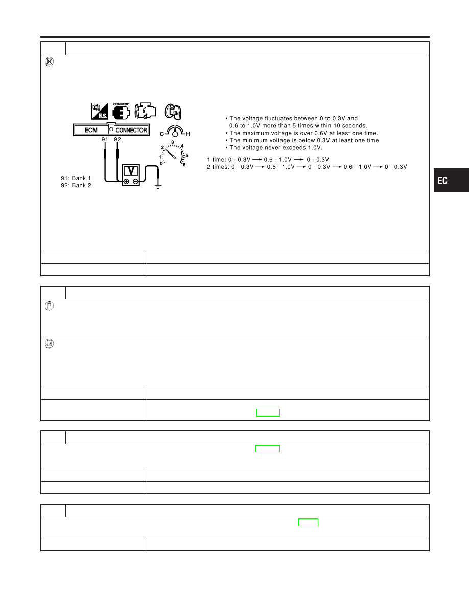
CHECK HEATED OXYGEN SENSOR 1
Without CONSULT-II
1. Start engine and warm it up to normal operating temperature.
2. Set voltmeter probes between ECM terminal 91 (HO2S1 bank 1 signal) or 92 (HO2S1 bank 2 signal) and ground.
3. Check the following with engine speed held at 2,000 rpm constant under no load.
SEC109D
CAUTION:
I
Discard any heated oxygen sensor which has been dropped from a height of more than 0.5 m (19.7 in) onto a
hard surface such as a concrete floor; use a new one.
I
Before installing new oxygen sensor, clean exhaust system threads using Oxygen Sensor Thread Cleaner tool
J-43897-18 or J-43897-12 and approved anti-seize lubricant.
OK or NG
OK
©
GO TO 12.
NG
©
Replace malfunctioning heated oxygen sensor 1.
12
CHECK MASS AIR FLOW SENSOR
With CONSULT-II
Check mass air flow sensor signal in “DATA MONITOR” mode with CONSULT-II.
2.0 - 6.0 g·m/sec: at idling
7.0 - 20.0 g·m/sec: at 2,500 rpm
With GST
Check mass air flow sensor signal in MODE 1 with GST.
2.0 - 6.0 g·m/sec: at idling
7.0 - 20.0 g·m/sec: at 2,500 rpm
OK or NG
OK
©
GO TO 13.
NG
©
Check connectors for rusted terminals or loose connections in the mass air flow sensor
circuit or engine grounds. Refer to EC-194.
13
CHECK SYMPTOM MATRIX CHART
Check items on the rough idle symptom in “Symptom Matrix Chart”, EC-127.
OK or NG
OK
©
GO TO 14.
NG
©
Repair or replace.
14
ERASE THE 1ST TRIP DTC
Erase the 1st trip DTC from the ECM memory after performing the tests. Refer to EC-88.
Some tests may cause a 1st trip DTC to be set.
©
GO TO 15.
GI
MA
EM
LC
FE
AT
AX
SU
BR
ST
RS
BT
HA
SC
EL
IDX
DTC P0300 - P0306 MULTIPLE CYLINDER MISFIRE, NO. 1 - 6 CYLINDER
MISFIRE
Diagnostic Procedure (Cont’d)
EC-309

15
CHECK INTERMITTENT INCIDENT
Refer to “TROUBLE DIAGNOSIS FOR INTERMITTENT INCIDENT”, EC-152.
©
INSPECTION END
DTC P0300 - P0306 MULTIPLE CYLINDER MISFIRE, NO. 1 - 6 CYLINDER
MISFIRE
Diagnostic Procedure (Cont’d)
EC-310
SEF332I
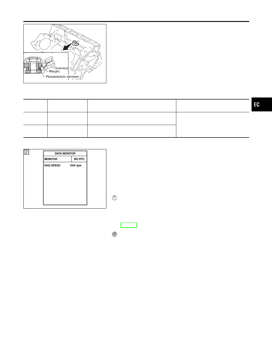
Component Description
NHEC0932
The knock sensor is attached to the cylinder block. It senses
engine knocking using a piezoelectric element. A knocking vibration
from the cylinder block is sensed as vibrational pressure. This
pressure is converted into a voltage signal and sent to the ECM.
On Board Diagnosis Logic
NHEC0934
The MIL will not light for these self-diagnoses.
DTC No.
Trouble diagnosis
name
DTC Detecting Condition
Possible Cause
P0327
0327
Knock sensor circuit
low input
An excessively low voltage from the sensor is sent
to ECM.
I
Harness or connectors
(The sensor circuit is open or
shorted.)
I
Knock sensor
P0328
0328
Knock sensor circuit
high input
An excessively high voltage from the sensor is
sent to ECM.
SEF058Y
DTC Confirmation Procedure
NHEC0935
NOTE:
If DTC Confirmation Procedure has been previously conducted,
always turn ignition switch OFF and wait at least 10 seconds before
conducting the next test.
TESTING CONDITION:
Before performing the following procedure, confirm that bat-
tery voltage is more than 10V at idle.
WITH CONSULT-II
NHEC0935S01
1)
Turn ignition switch ON and select “DATA MONITOR” mode
with CONSULT-II
2)
Start engine and run it for at least 5 seconds at idle speed.
3)
If 1st trip DTC is detected, go to “Diagnostic Procedure”,
EC-313.
WITH GST
NHEC0935S03
Follow the procedure “With CONSULT-II” above.
GI
MA
EM
LC
FE
AT
AX
SU
BR
ST
RS
BT
HA
SC
EL
IDX
DTC P0327, P0328 KS
Component Description
EC-311
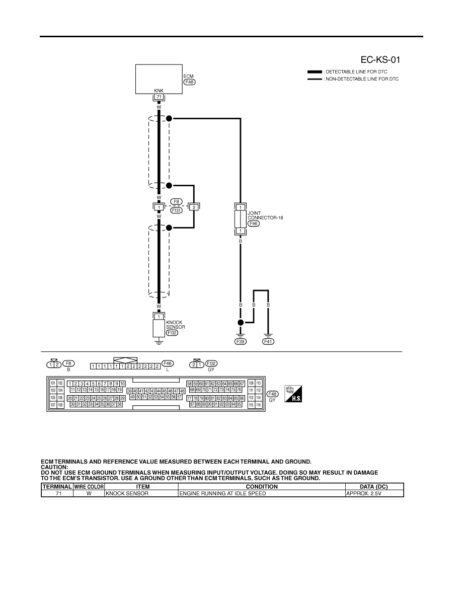
Wiring Diagram
NHEC0936
MEC550D
SEC117D
DTC P0327, P0328 KS
Wiring Diagram
EC-312
Нет комментариевНе стесняйтесь поделиться с нами вашим ценным мнением.
Текст