Infiniti I35 (A33). Manual — part 245
5
DETECT MALFUNCTIONING PART
Check the following.
I
Harness connectors F25, F171
I
Harness for open between harness connector F25 and ground
©
Repair open circuit or short to power in harness or connectors.
6
CHECK CKP SENSOR (POS) INPUT SIGNAL CIRCUIT FOR OPEN AND SHORT
1. Disconnect ECM harness connector.
2. Check harness continuity between ECM terminal 95 and harness connector F25 terminal 1.
Refer to Wiring Diagram.
Continuity should exist.
3. Also check harness for short to ground and short to power.
OK or NG
OK
©
GO TO 8.
NG
©
GO TO 7.
7
DETECT MALFUNCTIONING PART
Check the following.
I
Harness connectors F25, F171
I
Harness for open or short between ECM and harness connector F25
©
Repair open circuit or short to ground or short to power in harness or connectors.
8
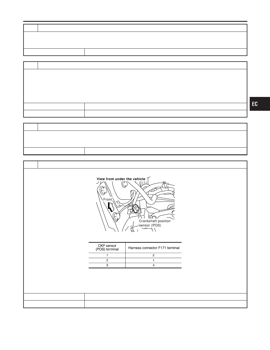
CHECK CKP SENSOR (POS) SUB-HARNESS CIRCUIT FOR OPEN AND SHORT
1. Disconnect CKP sensor (POS) harness connector.
SEC137D
2. Check harness continuity between CKP sensor (POS) terminals and harness connector F171 terminals as follows.
MTBL1191
Continuity should exist.
3. Also check harness for short to ground and short to power.
OK or NG
OK
©
GO TO 9.
NG
©
Repair open circuit or short to ground or short to power in harness or connectors.
GI
MA
EM
LC
FE
AT
AX
SU
BR
ST
RS
BT
HA
SC
EL
IDX
DTC P0335 CKP SENSOR (POS)
Diagnostic Procedure (Cont’d)
EC-321
9
CHECK CRANKSHAFT POSITION SENSOR (POS)
Refer to “Component Inspection”, EC-322.
OK or NG
OK
©
GO TO 10.
NG
©
Replace crankshaft position sensor (POS).
10
CHECK GEAR TOOTH
Visually check for chipping signal plate gear tooth.
OK or NG
OK
©
GO TO 11.
NG
©
Replace the signal plate.
11
CHECK INTERMITTENT INCIDENT
Refer to “TROUBLE DIAGNOSIS FOR INTERMITTENT INCIDENT”, EC-152.
©
INSPECTION END
PBIB0563E
Component Inspection
NHEC1415
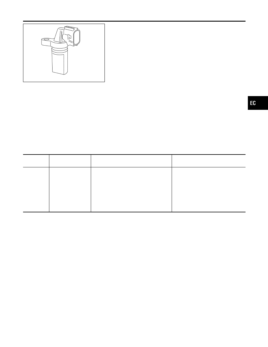
CRANKSHAFT POSITION SENSOR (POS)
NHEC1415S01
1.
Loosen the fixing bolt of the sensor.
2.
Disconnect crankshaft position sensor (POS) harness connec-
tor.
3.
Remove the sensor.
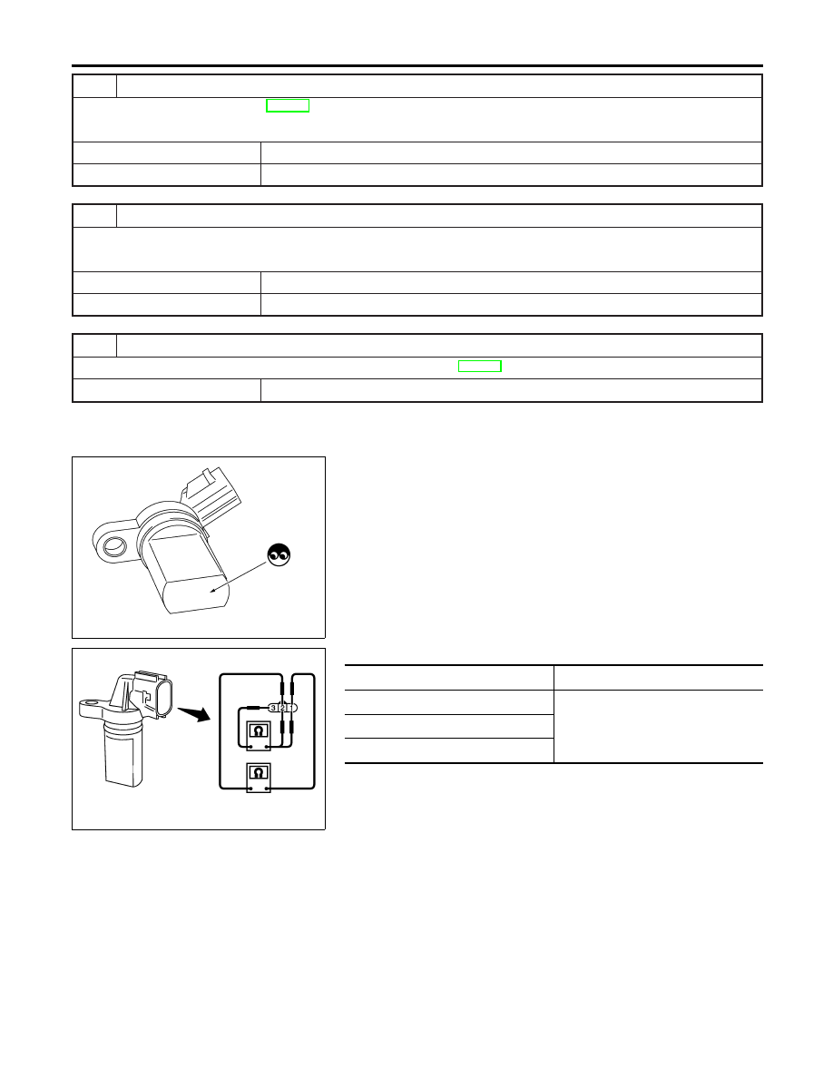
4.
Visually check the sensor for chipping.
SEC173D
5.
Check resistance as shown in the figure.
Terminal No. (Polarity)
Resistance
Ω
[at 25°C (77°F)]
1 (+) - 2 (−)
Except 0 or
∞
1 (+) - 3 (−)
2 (+) - 3 (−)
DTC P0335 CKP SENSOR (POS)
Diagnostic Procedure (Cont’d)
EC-322
PBIB0562E
Component Description
NHEC0945
The camshaft position sensor (PHASE) senses the retraction with
intake valve camshaft to identify a particular cylinder. The crank-
shaft position sensor (POS) senses the piston position. When the
crankshaft position sensor (POS) system becomes inoperative, the
camshaft position sensor (PHASE) provides various controls of
engine parts instead, utilizing timing of cylinder identification sig-
nals. The sensor consists of a permanent magnet and Hall IC.
When engine is running, the high and low parts of the teeth cause
the gap with the sensor to change. The changing gap causes the
magnetic field near the sensor to change. Due to the changing
magnetic field, the voltage from the sensor changes.
On Board Diagnosis Logic
NHEC0947
DTC No.
Trouble diagnosis
name
DTC Detecting Condition
Possible Cause
P0340
0340
(Bank 1)
P0345
0345
(Bank 2)
Camshaft position sen-
sor (PHASE) circuit
I
The cylinder No. signal is not sent to ECM
for the first few seconds during engine
cranking.
I
The cylinder No. signal is not sent to ECM
during engine running.
I
The cylinder No. signal is not in the normal
pattern during engine running.
I
Harness or connectors
[The camshaft position sensor
(PHASE) circuit is open or shorted.]
I
Camshaft position sensor (PHASE)
I
Camshaft (Intake)
I
Starter motor (Refer to SC section.)
I
Starting system circuit (Refer to SC
section.)
I
Dead (Weak) battery
DTC Confirmation Procedure
NHEC0948
NOTE:
If DTC Confirmation Procedure has been previously conducted,
always turn ignition switch OFF and wait at least 10 seconds before
conducting the next test.
TESTING CONDITION:
Before performing the following procedure, confirm that bat-
tery voltage is more than 10.5V with ignition switch ON.
GI
MA
EM
LC
FE
AT
AX
SU
BR
ST
RS
BT
HA
SC
EL
IDX
DTC P0340, P0345 CMP SENSOR (PHASE)
Component Description
EC-323
SEF058Y
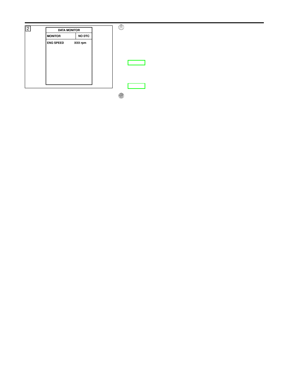
WITH CONSULT-II
NHEC0948S03
1)
Turn ignition switch ON.
2)
Select “DATA MONITOR” mode with CONSULT-II.
3)
Crank engine for at least 2 seconds and run it for at least 5
seconds at idle speed.
4)
If 1st trip DTC is detected, go to “Diagnostic Procedure”,
EC-327. If 1st trip DTC is not detected, go to next step.
5)
Maintaining engine speed at more than 1,000 rpm for at least
5 seconds.
6)
If 1st trip DTC is detected, go to “Diagnostic Procedure”,
EC-327.
WITH GST
NHEC0948S04
Follow the procedure “With CONSULT-II” above.
DTC P0340, P0345 CMP SENSOR (PHASE)
DTC Confirmation Procedure (Cont’d)
EC-324
Нет комментариевНе стесняйтесь поделиться с нами вашим ценным мнением.
Текст