Infiniti Q45 (FY33). Manual — part 437
SFA936B
SFA937B
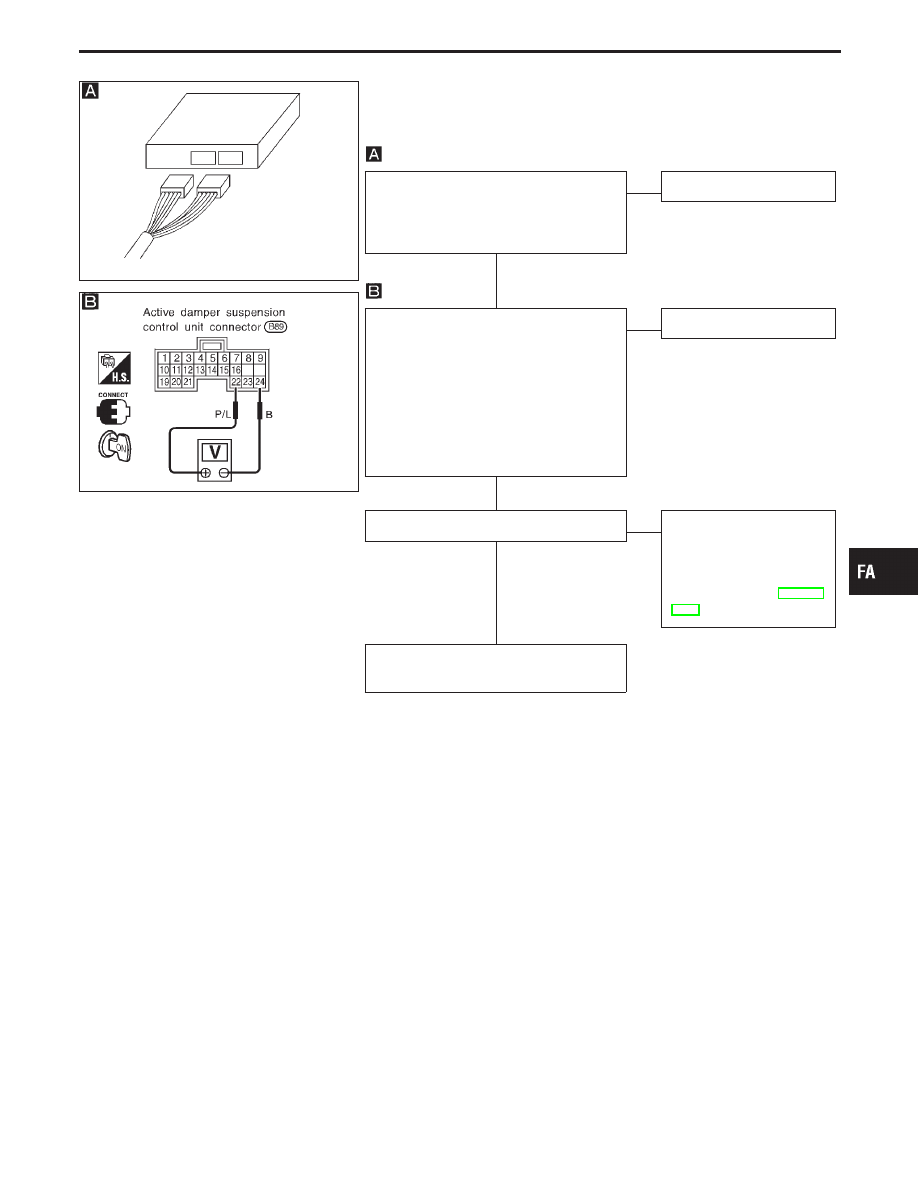
Diagnostic Procedure 1 (Vehicle speed sensor)
Code No. 11
Disconnect control unit connector, then
re-connect it securely. Perform self-diag-
nosis to check that proper test results are
obtained.
NG
E
OK
INSPECTION END
CHECK CONTROL UNIT INPUT SIG-
NAL.
1. Use a jack to raise the vehicle.
2. With vehicle operating at extremely low
speeds, measure vehicle speed sensor
input signal voltage between control
unit connector terminals
q
22
and
q
24
.
Voltage:
Varies from 0V to 5V.
NG
E
OK
Replace control unit.
Speedometer is operating properly.
OK
E
NG
Faulty speedometer circuit
(Refer to “Inspection/
Vehicle Speed Sensor Sig-
nal Circuit” of “METER
AND GAUGES” in EL sec-
tion.)
Faulty vehicle speed sensor or vehicle
speed sensor-to-control unit harness
GI
MA
EM
LC
EC
FE
AT
PD
RA
BR
ST
RS
BT
HA
EL
IDX
TROUBLE DIAGNOSES FOR SELF-DIAGNOSTIC ITEMS
H
H
H
FA-47
SFA938B
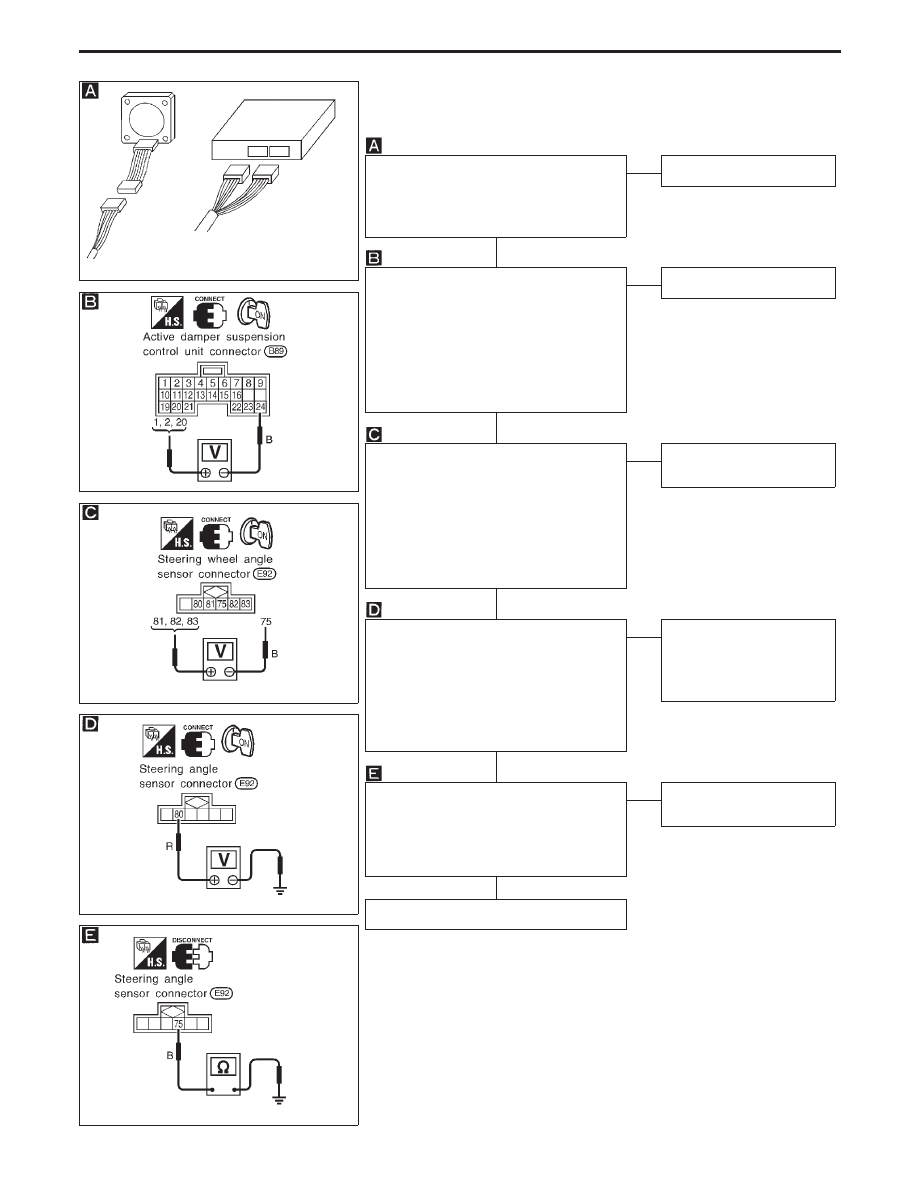
Diagnostic Procedure 2 (Steering angle sensor)
SFA939B
SFA940B
SFA941B
SFA942B
Code No. 12, 13
Disconnect control unit connector and
steering angle sensor connector, then re-
connect them securely. Perform self-diag-
nosis to check that proper test results are
obtained.
NG
E
OK
INSPECTION END
CHECK CONTROL UNIT INPUT SIG-
NAL.
1. Turn ignition switch to “ON”.
2. Slowly turn steering wheel at least 90°
to left or right from neutral. Measure
voltage between control unit connector
terminals
q
1
and
q
24
,
q
2
and
q
24
, and
q
20
and
q
24
.
Voltage:
Varies from 0V to 5V.
NG
E
OK
Replace control unit.
CHECK STEERING ANGLE SENSOR
OUTPUT SIGNAL.
1. Turn ignition switch to “ON”.
2. Slowly turn steering wheel at least 90°
to left or right from neutral. Measure
voltage between control unit connector
terminals
q
81
and
q
75
,
q
82
and
q
75
, and
q
83
and
q
75
.
Voltage:
Varies from 0V to 5V.
NG
E
OK
Faulty control unit-to-steer-
ing angle sensor harness
CHECK STEERING ANGLE SENSOR
POWER CIRCUIT.
1. Turn ignition switch to “ON”.
2. Slowly turn steering wheel at least 90°
to left or right from neutral. Measure
voltage between steering angle sensor
connector terminal
q
80
and body ground.
Voltage:
Battery voltage
OK
E
NG
Faulty power circuit.
Replace steering angle
sensor and repair faulty
power circuit. Perform self-
diagnosis again.
CHECK STEERING ANGLE SENSOR
GROUND CIRCUIT.
Check continuity between steering angle
sensor connector terminal
q
75
and body
ground.
Continuity should exist.
NG
E
OK
Replace steering angle
sensor.
Faulty ground harness.
TROUBLE DIAGNOSES FOR SELF-DIAGNOSTIC ITEMS
H
H
H
H
H
FA-48
SFA936B
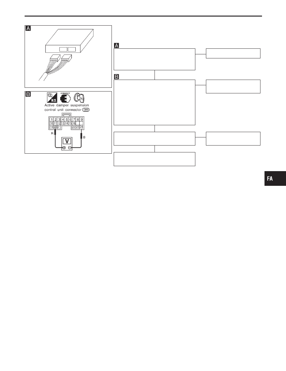
Diagnostic Procedure 3 (Stop lamp switch)
SFA943B
Code No. 14
Disconnect control unit connector, then
re-connect it securely. Perform self-diag-
nosis to check that proper test results are
obtained.
NG
E
OK
INSPECTION END
CHECK CONTROL UNIT INPUT SIG-
NAL.
1. Turn ignition switch to “ON”.
2. Measure voltage between control unit
connector terminals
q
11
and
q
24
.
Voltage:
Brake pedal depressed:
Approx. 12V
Brake pedal released:
0V
OK
E
NG
Faulty control unit-to-stop
lamp switch harness.
Check that stop lamps illuminate when
brake pedal is depressed.
NG
E
OK
Faulty control unit or con-
trol unit ground circuit.
Faulty battery-to-stop lamp switch harness
or stop lamp switch
GI
MA
EM
LC
EC
FE
AT
PD
RA
BR
ST
RS
BT
HA
EL
IDX
TROUBLE DIAGNOSES FOR SELF-DIAGNOSTIC ITEMS
H
H
H
FA-49
SFA944B
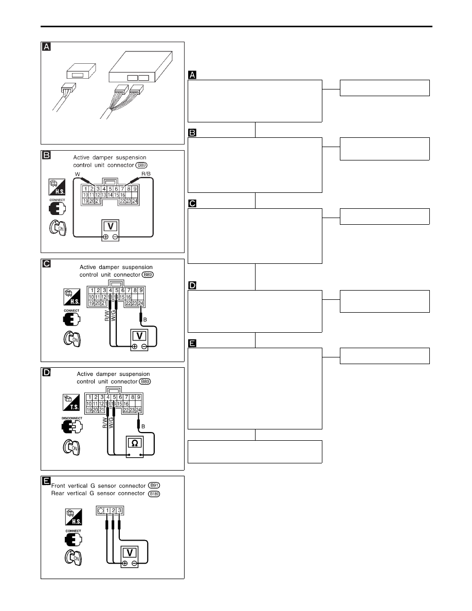
Diagnostic Procedure 4 (Vertical G sensor)
SFA945B
SFA005C
SFA006C
SFA947BA
Code No. 22, 23
Disconnect control unit connector and ver-
tical G sensor connector, then re-connect
them securely. Perform self-diagnosis to
check that proper test results are
obtained.
NG
E
OK
INSPECTION END
CHECK CONTROL UNIT VERTICAL G
SENSOR POWER CIRCUIT.
1. Turn ignition switch to “ON”.
2. Measure voltage between control unit
connector terminals
q
3
and
q
7
.
Voltage:
Approx. 5V
OK
E
NG
Faulty control unit or con-
trol unit ground circuit.
CHECK CONTROL UNIT VERTICAL G
SENSOR INPUT SIGNAL.
Measure voltage between control unit con-
nector terminals
q
4
and
q
24
,
q
5
and
q
24
,
and
q
24
.
Voltage:
Approx. 2.5V
NG
E
OK
Replace control unit.
CHECK CONTROL UNIT VERTICAL G
SENSOR INPUT SIGNAL CIRCUIT.
Check continuity between control unit con-
nector terminals
q
4
,
q
5
and
q
24
.
Continuity should not exist.
OK
E
NG
Faulty control unit-to-verti-
cal G sensor harness.
CHECK VERTICAL G SENSOR OUTPUT
SIGNAL.
1. Turn ignition switch to “ON”.
2. Measure voltage between vertical G
sensor connector terminals
q
1
and
q
3
and
q
2
and
q
3
.
Voltage:
q
1
—
q
3
Approx. 5V
q
2
—
q
3
Approx. 2.5V
OK
E
NG
Replace vertical G sensor.
Faulty control unit-to-vertical G sensor
harness.
Note: The front vertical G sensor is installed on the rear of the inner pil-
lar and the rear vertical G sensor is located on the rear of the outer
wheelhouse. To check each vertical G sensor output signal,
remove the vertical G sensor, set it vertical, then measure voltage
between terminals.
Be careful not to drop or bump the vertical G sensor as it is easy
to break. If dropped or bumped, replace with a new one.
TROUBLE DIAGNOSES FOR SELF-DIAGNOSTIC ITEMS
H
H
H
H
H
FA-50
Нет комментариевНе стесняйтесь поделиться с нами вашим ценным мнением.
Текст