Infiniti Q45 (FY33). Manual — part 435
Self-diagnoses
FUNCTION
The self-diagnosis system can be used without using CONSULT-
II. With this system, both self-diagnostic history and fail-safe history
are indicated by the SPORT indicator lamp.
SELF-DIAGNOSTIC PROCEDURE
1.
Turn ignition switch to “OFF”.
2.
Start the engine.
3.
Quickly switch the active damper suspension select switch
from “SPORT” to “AUTO”, and vice versa, at least 5 times
within 10 seconds immediately after the engine has started.
2 or 3 seconds following the above switch operation, the indi-
cator lamp will come on. This is not the indication of self-di-
agnosis.
4.
Perform the following procedures to enter the corresponding
signals.
I
Turn steering wheel 180° in either direction from neutral.
I
Depress brake pedal.
I
Release brake pedal.
I
Move the vehicle at least 5 m (16 ft) forward.
SFA931B
HOW TO READ SELF-DIAGNOSTIC RESULTS
(Malfunction codes)
Following the steps listed under the “Self-diagnostic procedure”
above, a faulty area or faulty areas, if any, are indicated by a
flashing active damper suspension indicator lamp located in the
meter cluster.
The indicator lamp flashes to show faulty areas corresponding with
No. 11 through 14, then No. 21, 23 and 24, in that order. 2 seconds
after all items are indicated, the indicator lamp repeats the flash
sequence for all items again.
I
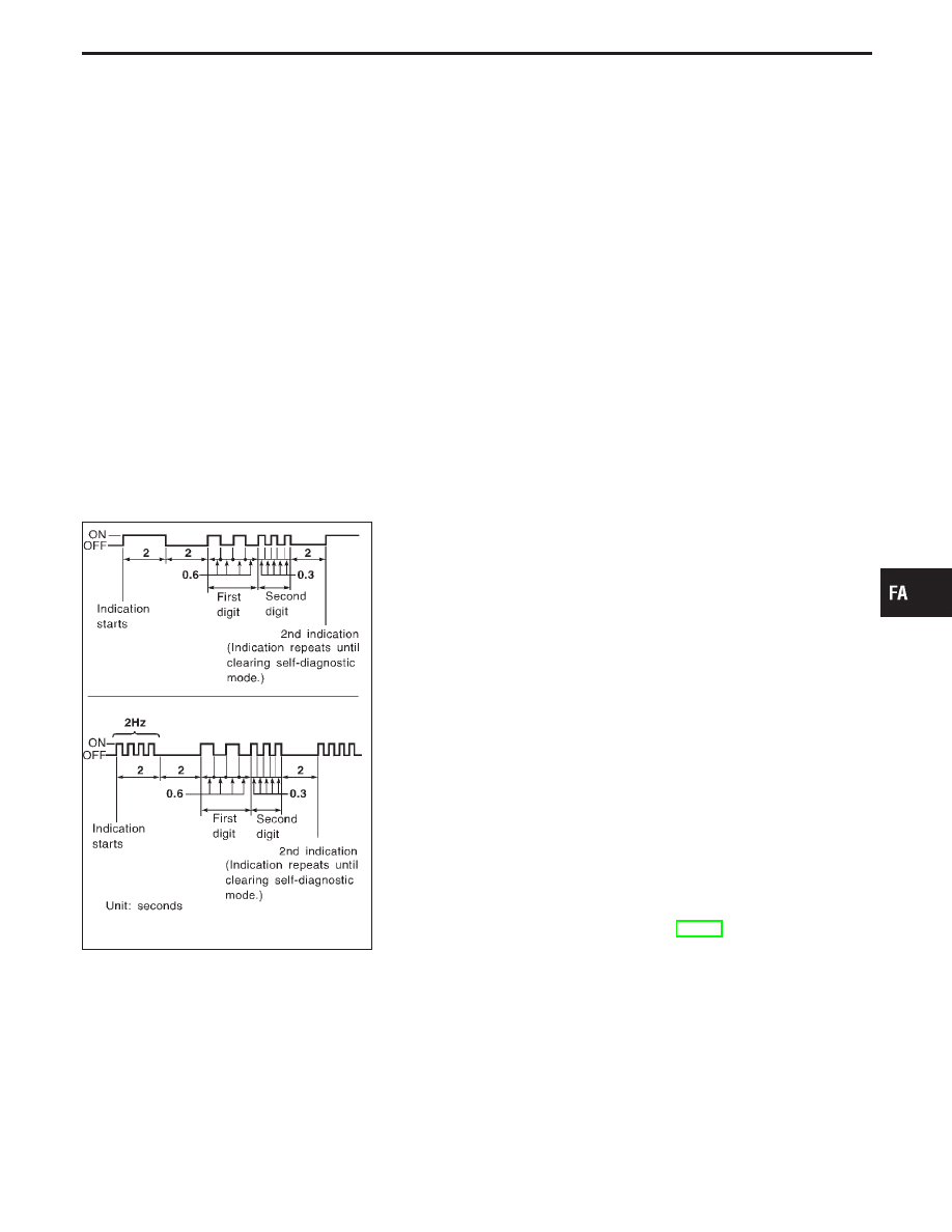
When all items are in good order, the indicator lamp flashes at
a cycle of 1/4 Hz [ON (2 seconds) and OFF (2 seconds)].
Display mode:
First digit “ON” (0.6 seconds)
Second digit “ON” (0.3 seconds)
I
The upper part of the figure at left shows an example of a faulty
area corresponding with No. 23.
I
The lower part of the figure at left shows an example of a faulty
area (No. 23) which previously fell under the fail-safe history
data and is still stored in the current fail-safe data history.
After repairing the faulty area(s), erase the self-diagnostic data
stored in memory. [Refer to “HOW TO ERASE SELF-DIAGNOS-
TIC RESULTS (Malfunction codes)”, FA-40].
GI
MA
EM
LC
EC
FE
AT
PD
RA
BR
ST
RS
BT
HA
EL
IDX
TROUBLE DIAGNOSES
FA-39
MALFUNCTION CODE/SYMPTOM CHART
Code No.
Diagnostic item
11
Vehicle speed sensor
12
Steering angle sensor
13
Steering angle (neutral) sensor
14
Stop lamp switch
22
Vertical G sensor (front)
23
Vertical G sensor (rear)
HOW TO ERASE SELF-DIAGNOSTIC RESULTS
(Malfunction codes)
Disconnecting the self-diagnostic function
Disconnect the self-diagnostic function using one of the following
three methods:
I
Turn the ignition switch to “OFF”.
I
Drive the vehicle at speeds greater than 30 km/h (19 MPH).
I
Connect CONSULT-II.
Clearing the self-diagnostic memory
Clear self-diagnostic data and fail-safe data stored in memory as
follows:
I
While self-diagnosis is being performed, depress the brake
pedal at least 5 times and shift the select switch position at
least 5 times. Pedal depression and switch shifting must be
done within 10 seconds during self-diagnosis.
TROUBLE DIAGNOSES
Self-diagnoses (Cont’d)
FA-40
CONSULT-II Inspection Procedure
The troubleshooting system provides four functional modes — self-
diagnosis, data monitor, active test and control unit part number
display modes.
Mode type
Description
Mode selection
Display representation
SELF-DIAG RESULTS
Self-diagnosis
The desired functional
mode can easily be
selected by means of
touch keys on CON-
SULT-II.
The desired functional
mode can easily be
shown on the CON-
SULT-II display.
DATA MONITOR
I
Helps locate main trouble cause according to a
self-diagnostic result.
I
Provides active damper suspension control unit
input and output monitoring and print-out func-
tion (observation and recording).
ACTIVE TEST
I
Used to precisely locate the main cause for
trouble according to the self-diagnostic result
obtained in the data monitor mode.
I
Provides operational checks of indicator light
and actuator circuits.
ECU PART NUMBER
Active damper control unit part numbers are
shown on the CONSULT-II display.
ECU (Active damper suspension control unit) part
number mode
Ignore the ECU part number displayed in the ECU PART NUMBER
MODE. Refer to parts catalog to order the ECU.
SEF046TA
SELF-DIAGNOSIS PROCEDURE
1.
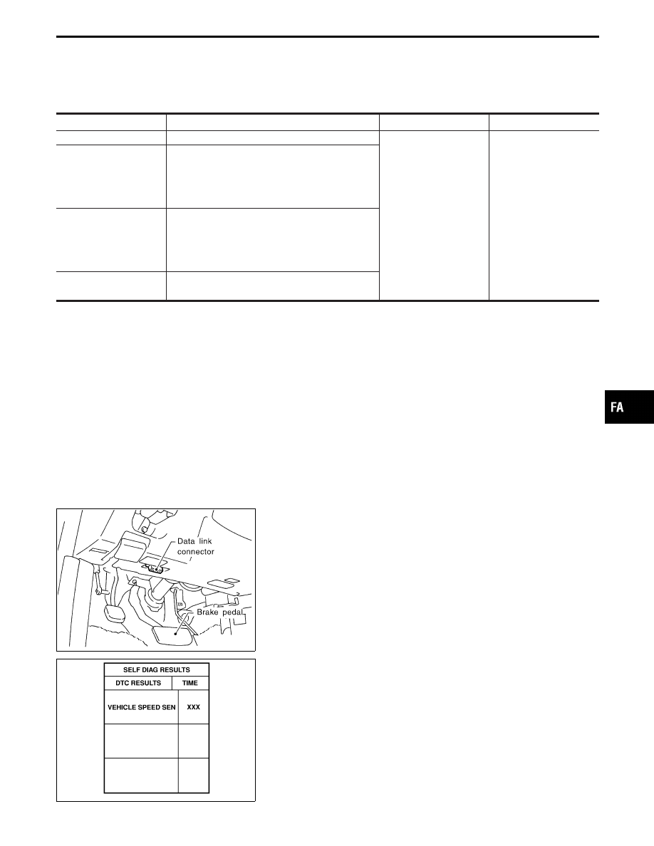
Connect CONSULT-II to data link connector and start the
engine.
SFA983B
2.
Touch “START”, “ACT D/SUS” and “SELF-DIAG RESULTS”.
1)
When a faulty item is displayed, record the item.
2)
Touch “ERASE”.
GI
MA
EM
LC
EC
FE
AT
PD
RA
BR
ST
RS
BT
HA
EL
IDX
TROUBLE DIAGNOSES
FA-41
SFA984B
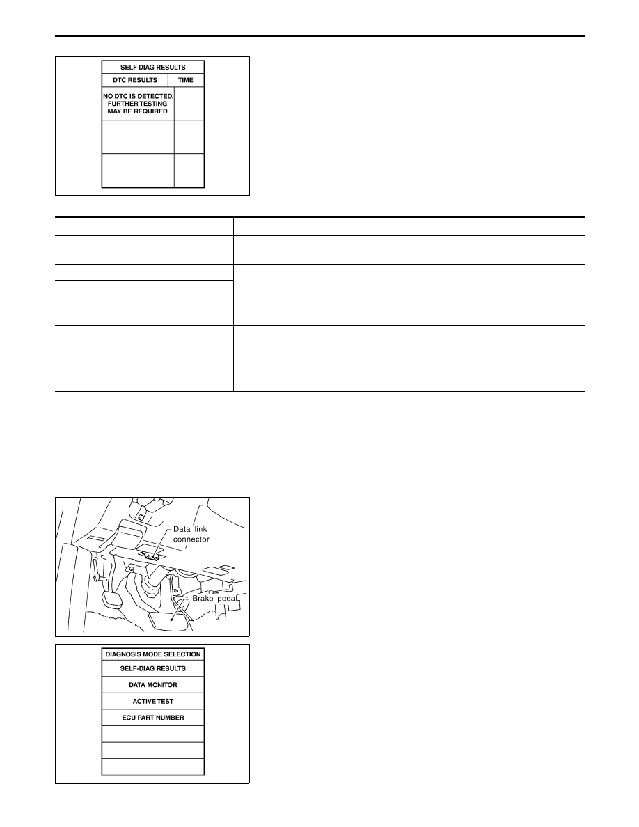
3.
A self-diagnostic result is displayed again.
If
“NO
SELF
DIAGNOSTIC
FAILURE
INDICATED”
is
displayed, check the item first shown on the display.
Items shown on display
Faulty system or circuit
Fault detecting conditions
VEHICLE SPEED SEN
I
Input signal does not change for some length of time while driving.
I
Input signal changes abruptly while driving.
VERTI G SENSOR F
I
Voltage is greater than or less than the standard value.
VERTI G SENSOR R/R
STEERING ANGLE SEN
[ANG SIGNAL] (.a)
Input signal does not change for some length of time while driving at speeds greater
than 60 km/h (37 MPH).
STEERING ANGLE SEN
[NEUT SIGNAL] (.b)
I
Neutral (“ON”) signal is not entered at all while driving a distance of more than 10
km (6 miles).
I
Neutral (“ON”) signal is not entered at all when steering wheel is turned at least
360°.
I
Neutral (“ON”) signal is entered when steering wheel is turned at least 50°.
SEF046TA
DATA MONITOR PROCEDURE
1.
Connect CONSULT-II to data link connector, then start the
engine.
PST412B
2.
Touch “START”, “ACT D/SUS” and “DATA MONITOR”.
TROUBLE DIAGNOSES
CONSULT-II Inspection Procedure (Cont’d)
FA-42
Нет комментариевНе стесняйтесь поделиться с нами вашим ценным мнением.
Текст