Infiniti Q45 (FY33). Manual — part 436
SFA985B
3.
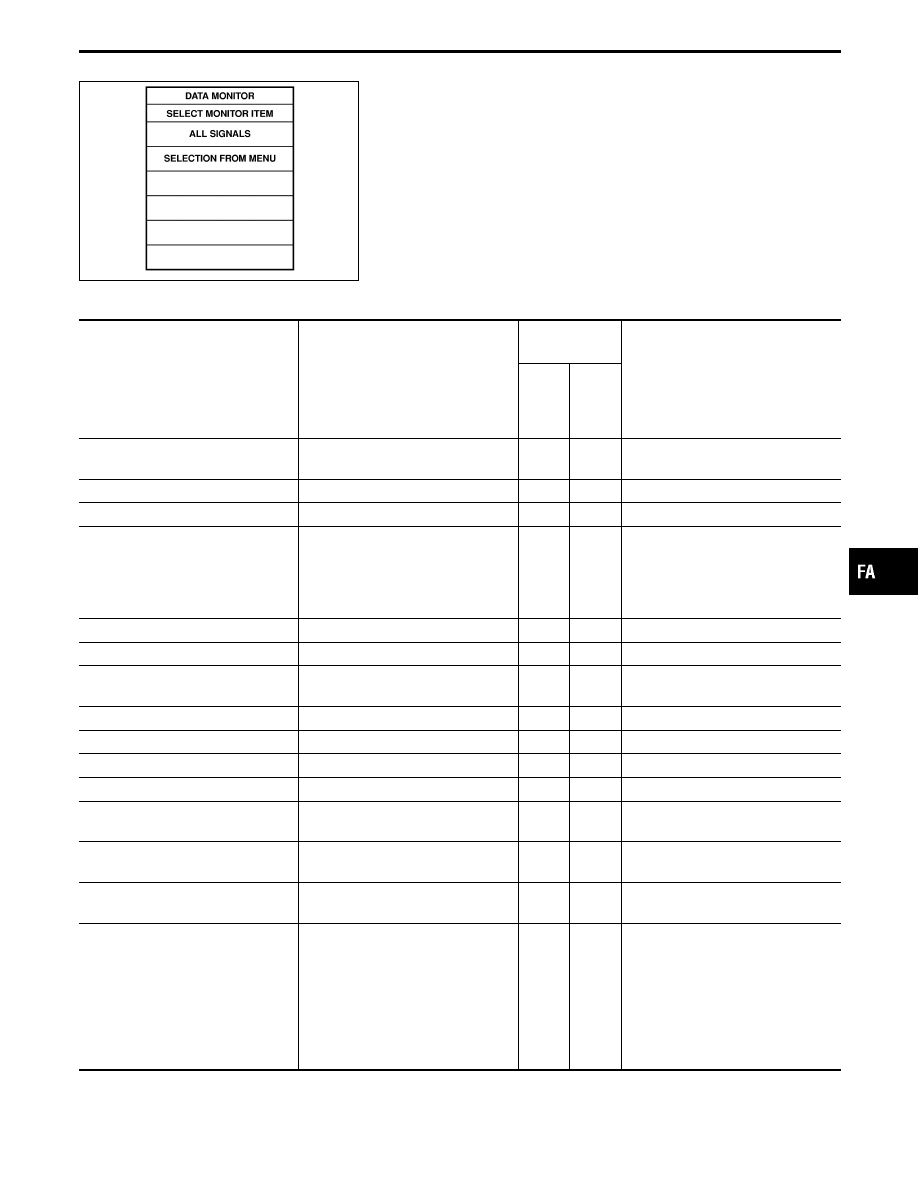
Select the signal to be monitored.
1)
When “ALL SIGNALS” is selected, touch “START”.
2)
When “SELECTION FROM MENU” is to be selected, touch
“SETTING”. “MONITOR ITEM MENU” will then be indicated on
the display. Touch the item to be monitored, then “ENTER” and
“START”.
3)
Print out the data if necessary.
DATA MONITOR MODE
Monitored item
Display
Data item selec-
tion
Remarks
Main
item
Item
menu
selec-
tion
Vehicle speed sensor
VHCL SPEED SE
[km/h] or [mph]
q
q
—
Vertical G sensor front
VERTI G SE F [G]
q
q
—
Vertical G sensor rear right side
VERTI G SE RR [G]
q
q
—
Steering angle sensor (steering
angle signal)
STEERING ANG [°]
q
q
When the battery is disconnected
and then reconnected, an abnormal
value is displayed until the straight-
ahead position (0°) is set during
driving.
Active damper select switch
SELECT SWITCH [AUTO-SPORT]
q
q
—
Stop lamp switch
STOP LAMP SW [ON-OFF]
q
q
—
Steering angle sensor (steering neu-
tral signal)
NEUTRAL SIG [ON-OFF]
q
q
—
Damper motor front right
DAMP MTR F/R [Step]
q
q
—
Damper motor front left
DAMP MTR F/L [Step]
q
q
—
Damper motor rear right
DAMP MTR R/R [Step]
q
q
—
Damper motor rear left
DAMP MTR R/L [Step]
q
q
—
Power steering solenoid valve
POWER STR SOL [A]
q
q
EPS solenoid control current flow
from control unit
Active damper indicator lamp
(SPORT)
INDICATOR [ON-OFF]
q
q
—
Voltage
ê
VOLTAGE [V]
—
q
Voltage measured by the voltage
probe.
Pulse
ê
PULSE [msec] or [Hz] or [%]
—
q
Pulse width, frequency or duty cycle
measured by the pulse probe. Only
“#” is displayed if item is unable to
be measured.
Figures with “#”s are temporary
ones. They are the same figures as
an actual piece of data which was
just previously measured.
GI
MA
EM
LC
EC
FE
AT
PD
RA
BR
ST
RS
BT
HA
EL
IDX
TROUBLE DIAGNOSES
CONSULT-II Inspection Procedure (Cont’d)
FA-43
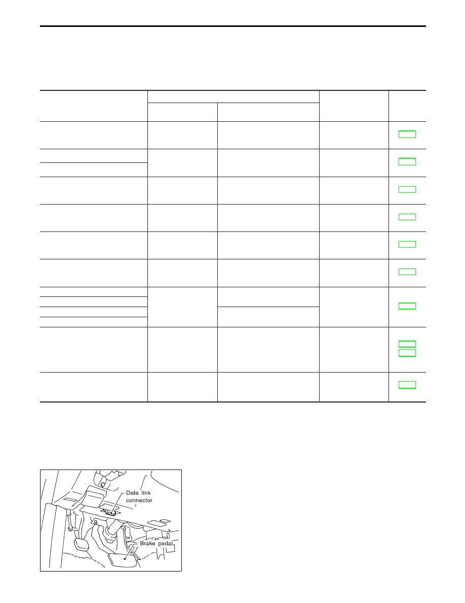
Specifications for control unit input and output signals
Standard values emitted by CONSULT-II
Output signals refer to the data which are operated by the
control unit. If an output circuit (harness) is broken, normal
values are displayed.
Items to monitor
Data monitor
Items to check
(when abnormal)
Reference
page
Conditions
Reference value
(when normal)
VHCL SPEED SE [km/h] or [mph]
During driving or drive
wheel rotation
Corresponds with
speedometer indication.
Vehicle speed sensor
circuit (Refer to “Diag-
nostic Procedure 1”.)
VERTI G SE F [G]
Vehicle is stopped on
a flat road.
Within ±0.15G
Vertical G sensor cir-
cuit (Refer to “Diag-
nostic Procedure 4”.)
VERTI G SE RR [G]
STEERING ANG [°]
Steering wheel is
turned in either direc-
tion.
Steering wheel angle from neu-
tral is displayed.
Steering angle sensor
circuit (Refer to “Diag-
nostic Procedure 2”.)
SELECT SW [AUTO-SPORT]
Select switch position
Set to “AUTO”: AUTO
Set to “SPORT”: SPORT
Select switch circuit
(Refer to “Diagnostic
Procedure 5”.)
STOP LAMP SW [ON-OFF]
Brake pedal position
Brake pedal is depressed. : ON
Brake pedal is released. : OFF
Stop lamp switch cir-
cuit (Refer to “Diag-
nostic Procedure 3”.)
NEUTRAL SIG [ON-OFF]
Steering wheel is set
at neutral or is turned
in either direction.
Neutral position: ON
Other position: OFF
Steering angle sensor
circuit (Refer to “Diag-
nostic Procedure 2”.)
DAMP MTR F/R [Step]
Actuator position
16 step
Shock absorber
actuator circuit (Refer
to “Diagnostic Proce-
dure 6”.)
DAMP MTR F/L [Step]
DAMP MTR R/R [Step]
16 step
DAMP MTR R/L [Step]
POWER STR SOL [A]
Increase vehicle
speed from 0 to 100
km/h (0 to 62 MPH).
0 km/h (0 MPH):
Approx. 1.1A
100 km/h (62 MPH):
Approx. 0.47A
EPS solenoid circuit
(Refer to “Diagnostic
Procedure 7” and
“Diagnostic Procedure
8”.)
INDICATOR [ON-OFF]
Ignition switch is
turned to “ON” or
engine is operating.
Indicator lamp is on. : ON
Indicator lamp is off. : OFF
Indicator lamp circuit
(Refer to “Diagnostic
Procedure 5”.)
SEF046TA
ACTIVE TEST PROCEDURE
1.
Connect CONSULT-II to data link connector, then start the
engine.
TROUBLE DIAGNOSES
CONSULT-II Inspection Procedure (Cont’d)
FA-44
PST412B
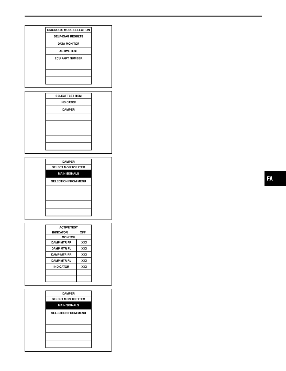
2.
Touch “START”, “ACT D/SUS” and “ACTIVE TEST”.
SFA986B
3.
Touch “INDICATOR” or “DAMPER” as required.
SFA987B
I
When “INDICATOR” is to be selected:
1)
Touch “MAIN SIGNAL”, then “START”.
SFA988B
2)
When “OFF” is touched, indicator lamp goes out regardless of
select switch positions. Monitor indicator will then be turned
“OFF”.
3)
When “ON” is touched, indicator lamp comes on regardless of
select switch positions. Monitor indicator will then be turned
“ON”.
SFA987B
I
When “DAMPER” is to be selected:
1)
Touch “SELECTION FROM MENU”.
2)
Select and touch “DAMP MTR F/R” or “DAMP MTR F/L”, and
“DAMP MTR R/R” or “DAMP MTR R/L”, as required.
3)
Touch “ENTER”, then “START”.
GI
MA
EM
LC
EC
FE
AT
PD
RA
BR
ST
RS
BT
HA
EL
IDX
TROUBLE DIAGNOSES
CONSULT-II Inspection Procedure (Cont’d)
FA-45
SFA989B
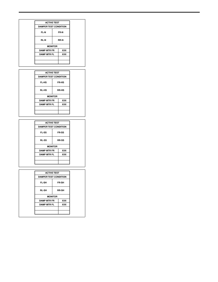
4)
“4 step” for front damper motors and “4 step” for rear damper
motor will be then shown on the display.
5)
Touch “CONDITION CHANGE”, “FL-N, FR-N, RL-N, RR-N”
and “START”.
SFA990B
6)
“96 step” for front damper motors and “96 step” for rear damper
motor will then appear on the display.
7)
Touch “CONDITION CHANGE”, “FL-HS, FR-HS, RL-HS,
RR-HS” and “START”.
SFA991B
8)
“0 step” for front damper motors and “0 step” for rear damper
motor will then appear on the display.
9)
Touch “CONDITION CHANGE” and “FL-SS, FR-SS, RL-SS,
RR-SS” and “START”.
SFA992B
10) “−40 step” for front damper motors and “−40 step” for rear
damper motor will then appear on the display.
11) Print out data as required.
TROUBLE DIAGNOSES
CONSULT-II Inspection Procedure (Cont’d)
FA-46
Нет комментариевНе стесняйтесь поделиться с нами вашим ценным мнением.
Текст