Infiniti Q45 (FY33). Manual — part 266
SEL070Y
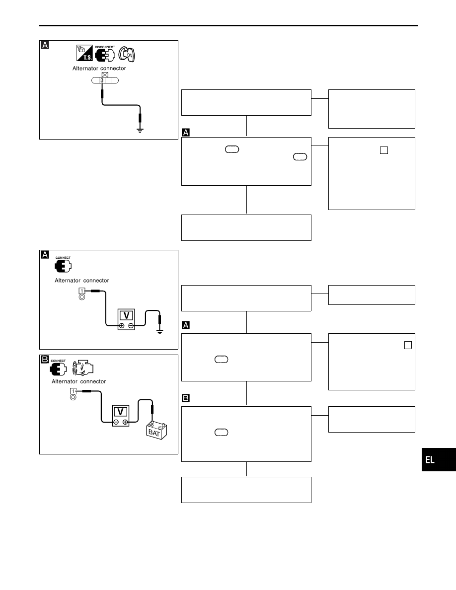
DIAGNOSTIC PROCEDURE 1
(“L” terminal circuit check)
CHECK “L” TERMINAL CONNECTION.
Check to see if “L” terminal is clean and
tight.
OK
E
NG
Repair “L” terminal connec-
tion. Confirm repair by per-
forming complete Battery/
Starting/Charging system
test.
CHECK “L” TERMINAL CIRCUIT.
1. Disconnect
E108
connector.
2. Apply ground to harness connector
E108
terminal
q
3
(W/R) with the ignition
switch in the ON position.
CHARGE lamp should light up.
OK
E
NG
Check the following.
I
7.5A fuse [No.
4
, located
in fuse block (J/B)]
I
CHARGE lamp
I
Harness for open or short
between combination
meter and fuse
I
Harness for open or short
between combination
meter and alternator
Replace the alternator.
Confirm repair by performing complete
Battery/Starting/Charging system test.
SEL071Y
DIAGNOSTIC PROCEDURE 2
(“B” terminal circuit check)
SEL072Y
CHECK “B” TERMINAL CONNECTION.
Check to see if “B” terminal is clean and
connected tightly.
OK
E
NG
Repair “B” terminal connec-
tion.
CHECK ALTERNATOR “B” TERMINAL
CIRCUIT.
Check voltage between alternator harness
connector
E107
terminal
q
1
(B/R) and
ground using a digital circuit tester.
Battery voltage should exist.
OK
E
NG
Check the following.
I
120A fusible link (letter a ,
located in fuse and fus-
ible link box)
I
Harness for open or short
between alternator and
fusible link
CHECK “B” TERMINAL CONNECTION
QUALITY (VOLTAGE DROP TEST).
Check voltage between alternator harness
connector
E107
terminal
q
1
(B/R) and bat-
tery positive terminal using a digital tester.
When the engine running at idle and warm:
Voltage: Less than 0.2V
OK
E
NG
Check harness between the
battery and the alternator
for poor continuity.
Replace the alternator.
Confirm repair by performing complete
Battery/Starting/Charging system test.
GI
MA
EM
LC
EC
FE
AT
PD
FA
RA
BR
ST
RS
BT
HA
IDX
CHARGING SYSTEM
Trouble Diagnoses with
Battery/Starting/Charging System Tester
(Cont’d)
H
H
H
H
H
EL-55
SEL073Y
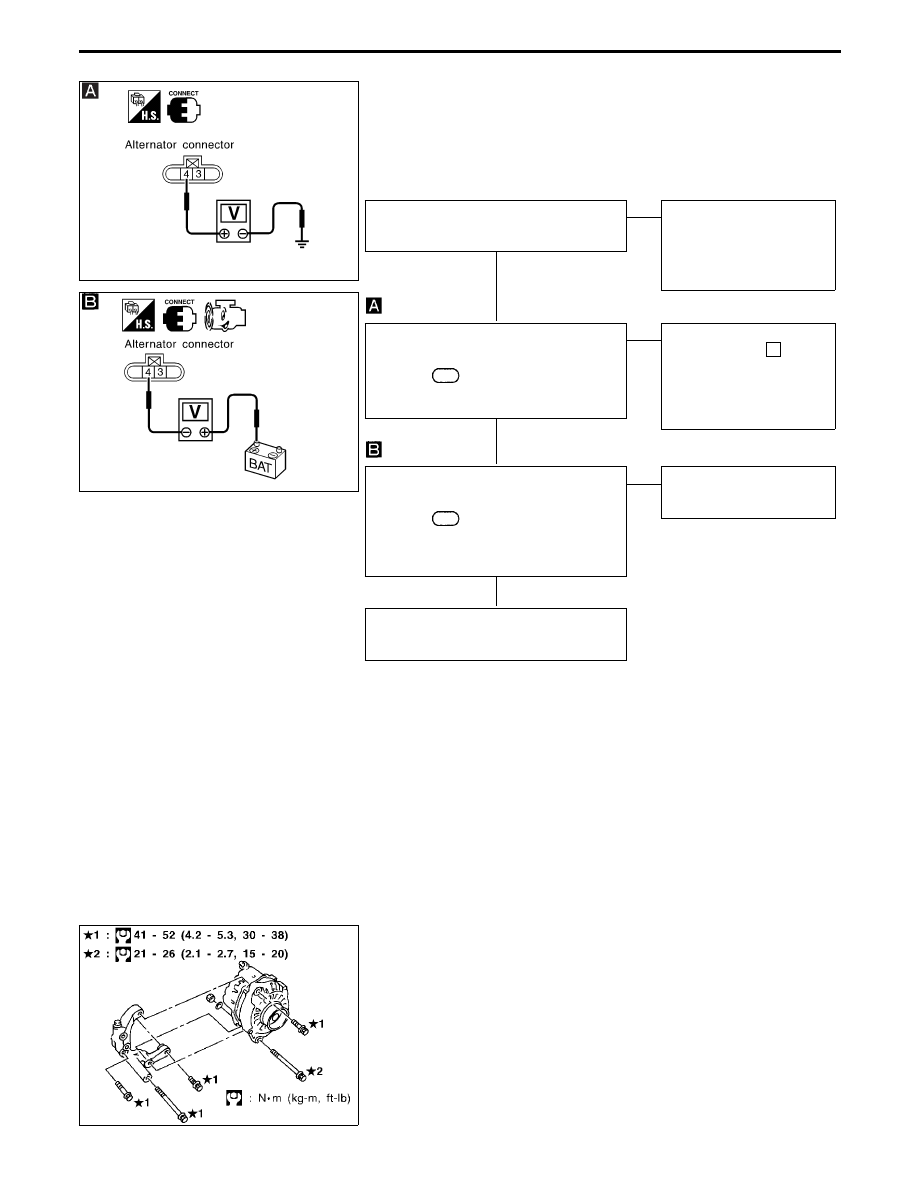
DIAGNOSTIC PROCEDURE 3
(“S” terminal circuit check)
SEL074Y
CHECK “S” TERMINAL CONNECTION.
Check to see if “S” terminal is clean and
tight.
OK
E
NG
Repair “S” terminal connec-
tion.
Confirm repair by perform-
ing complete Battery/
Starting/Charging system
test.
CHECK ALTERNATOR “S” TERMINAL
CIRCUIT.
Check voltage between alternator harness
connector
E108
terminal
q
4
(Y/R) and
ground using a digital circuit tester.
Battery voltage should exist.
OK
E
NG
Check the following.
I
7.5A fuse (No.
62
,
located in fuse and fus-
ible link box)
I
Harness for open or short
between alternator and
fuse
CHECK “S” TERMINAL CONNECTION
QUALITY (VOLTAGE DROP TEST).
Check voltage between alternator harness
connector
E108
terminal
q
4
(Y/R) and bat-
tery positive terminal using a digital tester.
When the engine running at idle and warm:
Voltage: Less than 0.2V
OK
E
NG
Check harness between the
battery and the alternator
for poor continuity.
Replace the alternator.
Confirm repair by performing complete
Battery/Starting/Charging system test.
MALFUNCTION INDICATOR
The
IC
regulator
warning
function
activates
to
illuminate
“CHARGE” warning lamp, if any of the following symptoms occur
while alternator is operating:
I
Excessive voltage is produced.
I
No voltage is produced.
MEL585G
Removal and Installation
REMOVAL
1.
Remove engine upper cover.
2.
Remove drive belt from alternator.
3.
Disconnect harness connector.
4.
Remove alternator.
INSTALLATION
To install, reverse the removal procedure.
CHARGING SYSTEM
Trouble Diagnoses with
Battery/Starting/Charging System Tester
(Cont’d)
H
H
H
EL-56
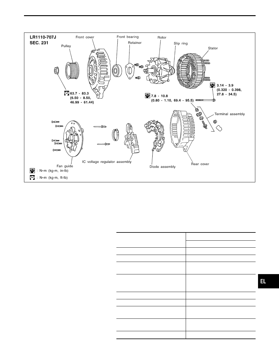
Construction
SEL276VG
Service Data and Specifications (SDS)
ALTERNATOR
Type
LR1110-707J
HITACHI make
Nominal rating
V-A
12-110
Ground polarity
Negative
Minimum revolution under no-load
(When 13.5 volts is applied)
rpm
Less than 950
Hot output current
(When 13.5 volts is applied)
A/rpm
More than 34/1,300
More than 82/2,500
More than 105/5,000
Regulated output voltage
V
14.1 - 14.7
Minimum length of brush
mm (in)
6.0 (0.236)
Brush spring pressure
N (g, oz)
1.000 - 3.432
(102 - 350, 3.60 - 12.34)
Slip ring minimum outer diameter
mm (in)
26.0 (1.024)
Rotor (Field coil) resistance
Ω
2.31
GI
MA
EM
LC
EC
FE
AT
PD
FA
RA
BR
ST
RS
BT
HA
IDX
CHARGING SYSTEM
EL-57
Check
CEL994
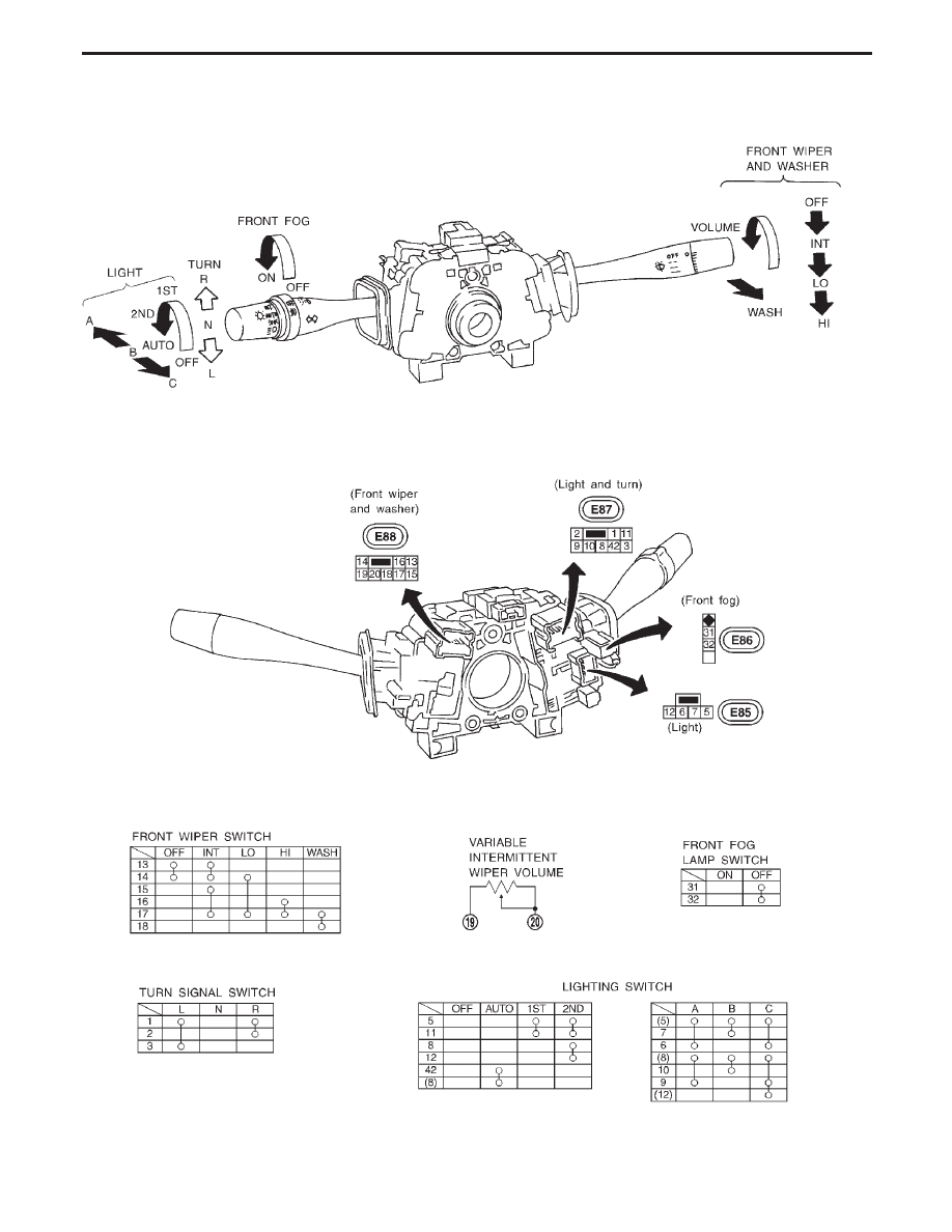
COMBINATION SWITCH
EL-58
Нет комментариевНе стесняйтесь поделиться с нами вашим ценным мнением.
Текст