Infiniti Q45 (FY33). Manual — part 264
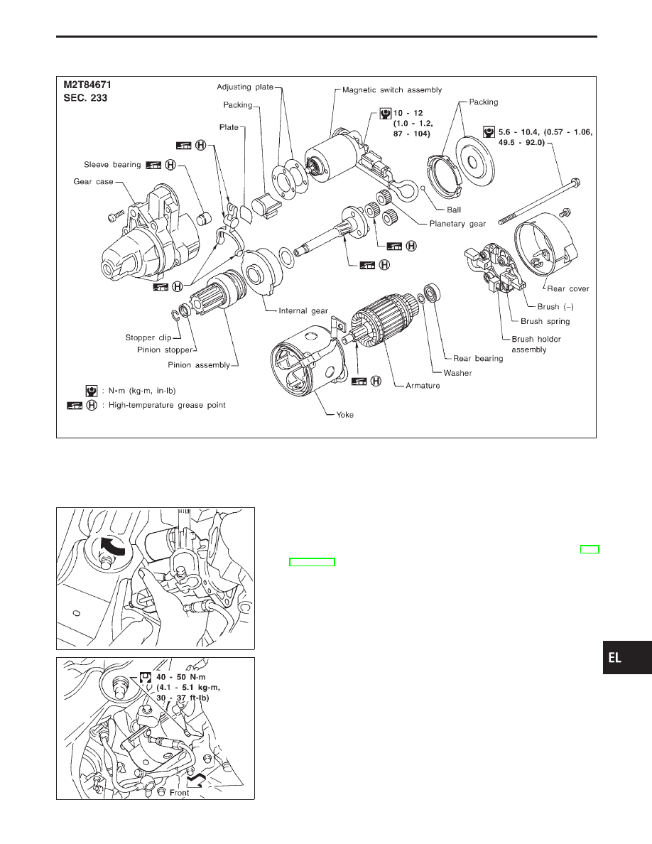
Construction
MEL581G
MEL583G
Removal and Installation
REMOVAL
1.
Remove steering gear and linkage assembly. (Refer to “ST
section”.)
2.
Remove harness connector.
3.
Remove starter by moving it in the direction of the arrow.
MEL582G
INSTALLATION
To install, reverse the removal procedure.
GI
MA
EM
LC
EC
FE
AT
PD
FA
RA
BR
ST
RS
BT
HA
IDX
STARTING SYSTEM
EL-47

Pinion/Clutch Check
1.
Inspect pinion teeth.
I
Replace pinion if teeth are worn or damaged. (Also check
condition of ring gear teeth.)
2.
Inspect reduction gear teeth.
I
Replace reduction gear if teeth are worn or damaged. (Also
check condition of armature shaft gear teeth.)
3.
Check to see if pinion locks in one direction and rotates
smoothly in the opposite direction.
I
If it locks or rotates in both directions, or unusual resistance is
evident, replace.
Service Data and Specifications (SDS)
STARTER
Type
M2T84671
MITSUBISHI make
Reduction gear type
System voltage
V
12
No-load
Terminal voltage
V
11.0
Current
A
Less than 145
Revolution
rpm
More than 3,300
Minimum diameter of commutator
mm (in)
31.4 (1.236)
Minimum length of brush
mm (in)
11.0 (0.433)
Brush spring tension
N (kg, lb)
30.9 - 37.7
(3.15 - 3.85, 6.95 - 8.47)
Clearance between pinion front edge and pinion
stopper
mm (in)
0.5 - 2.0 (0.020 - 0.079)
STARTING SYSTEM
EL-48

System Description
The alternator provides DC voltage to operate the vehicle’s electrical system and to keep the battery charged.
The voltage output is controlled by the IC regulator.
Power is supplied at all times to alternator terminal
q
S
through:
I
120A fusible link (letter
a
, located in the fuse, fusible link and relay box), and
I
7.5A fuse (No.
62
, located in the fuse, fusible link and relay box).
Terminal
q
B
supplies power to charge the battery and operate the vehicle’s electrical system. Output voltage
is controlled by the IC regulator at terminal
q
S
detecting the input voltage. The charging circuit is protected by
the 120A fusible link.
Terminal
q
E
of the alternator supplies ground through body ground
E112
.
With the ignition switch in the ON or START position, power is supplied
I
through 7.5A fuse [No.
4
, located in the fuse block (J/B)]
I
to combination meter terminal
q
41
for the charge warning lamp.
Ground is supplied to terminal
q
25
of the combination meter through terminal
q
L
of the alternator. With power
and ground supplied, the charge warning lamp will illuminate. When the alternator is providing sufficient volt-
age with the engine running, the ground is opened and the charge warning lamp will go off.
If the charge warning lamp illuminates with the engine running, a fault is indicated.
GI
MA
EM
LC
EC
FE
AT
PD
FA
RA
BR
ST
RS
BT
HA
IDX
CHARGING SYSTEM
EL-49
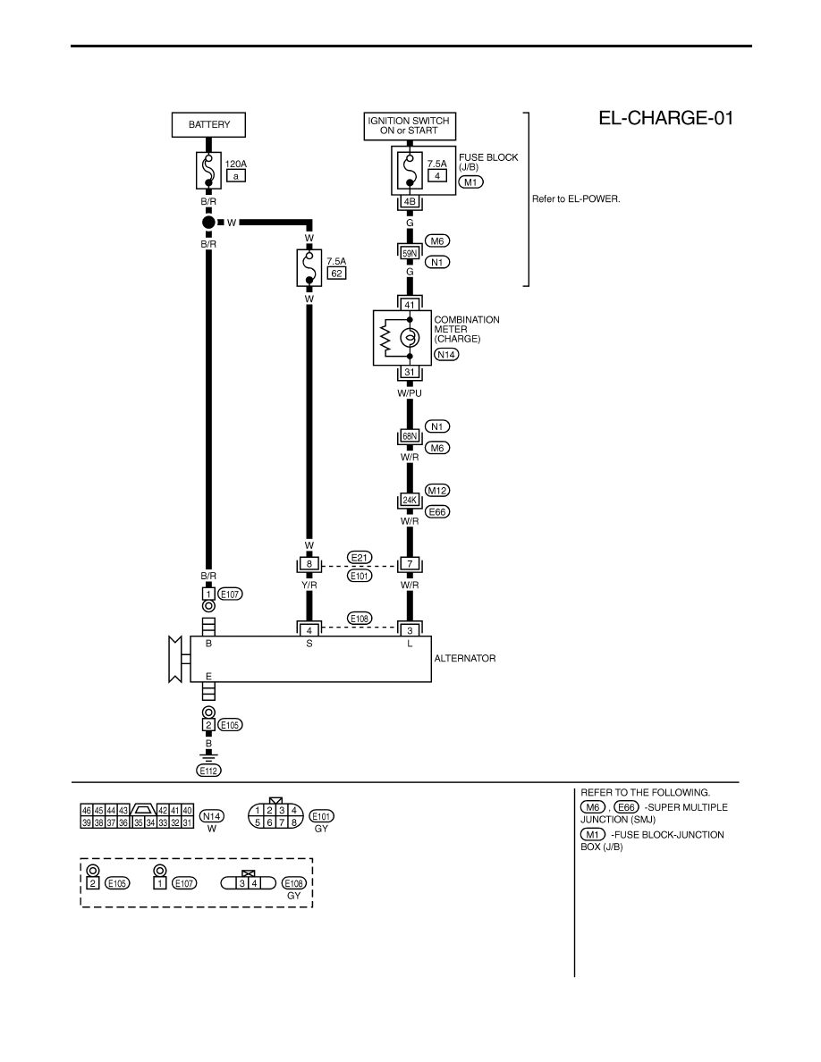
Wiring Diagram — CHARGE —
TEL051M
CHARGING SYSTEM
EL-50
Нет комментариевНе стесняйтесь поделиться с нами вашим ценным мнением.
Текст