Infiniti Q45 (FY33). Manual — part 267
CEL501
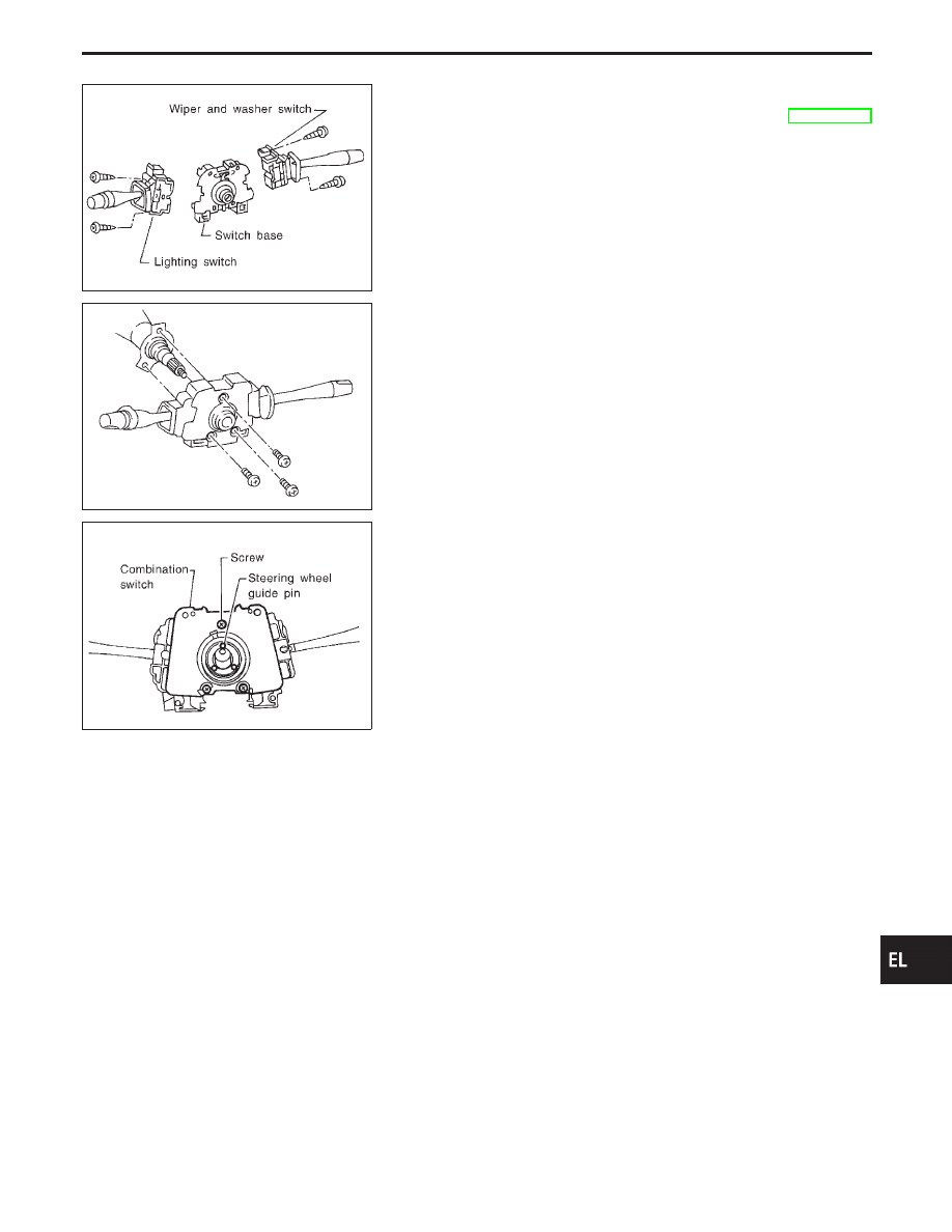
Replacement
For removal and installation of spiral cable, refer to RS section
[“SUPPLEMENTAL RESTRAINT SYSTEM (SRS)”, “Installation
— Air Bag Module and Spiral Cable”].
I
Each switch can be replaced without removing combination
switch base.
CEL406
I
To remove combination switch base, remove base attaching
screw.
SEL151V
I
Before installing steering wheel, align the steering wheel guide
pins with the screws which secure the combination switch, as
shown in the left figure.
GI
MA
EM
LC
EC
FE
AT
PD
FA
RA
BR
ST
RS
BT
HA
IDX
COMBINATION SWITCH
EL-59
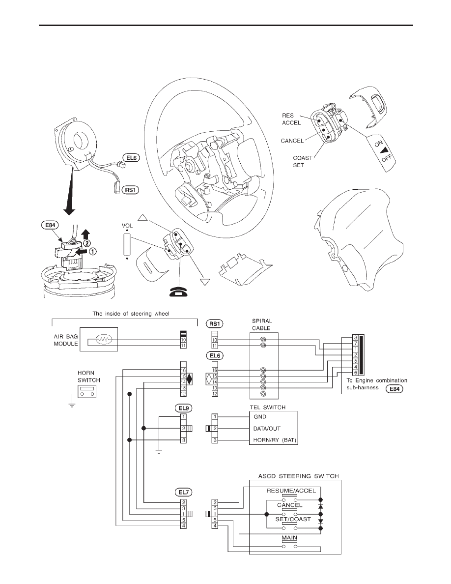
Check
WITH INFINITI COMMUNICATOR (IVCS)
CEL995
STEERING SWITCH
EL-60
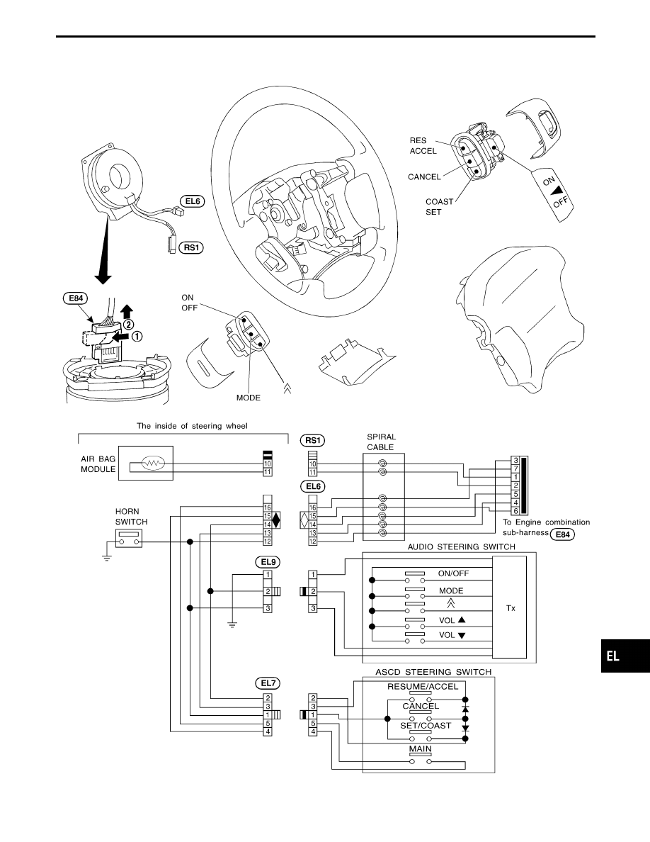
WITHOUT INFINITI COMMUNICATOR (IVCS)
CEL846
GI
MA
EM
LC
EC
FE
AT
PD
FA
RA
BR
ST
RS
BT
HA
IDX
STEERING SWITCH
Check (Cont’d)
EL-61
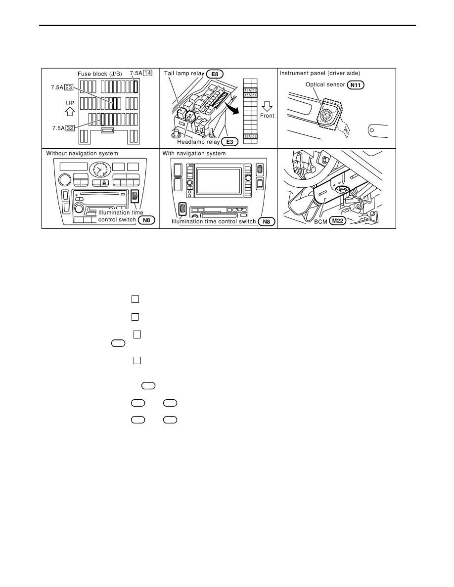
Component Parts and Harness Connector
Location
SEL141Y
System Description
Power is supplied at all times
I
to headlamp relay terminal
q
1
, and
I
through 15A fuse [No.
53
, located in the fuse, fusible link and relay box]
I
to headlamp relay terminal
q
5
, and
I
through 15A fuse [No.
54
, located in the fuse, fusible link and relay box]
I
to headlamp relay terminal
q
7
, and
I
through 7.5A fuse [No.
14
, located in the fuse block (J/B)].
I
to BCM terminal
105
.
When the ignition switch is in the ON or START position, power is supplied
I
through 7.5A fuse [No.
32
, located in the fuse block (J/B)]
I
to BCM terminal
q
68
.
Ground is supplied
I
to BCM terminals
q
56
and
113
I
to illumination time control switch terminal
q
3
I
through body grounds
M14
and
M47
, and
I
to the lighting switch terminals
q
8
and
q
5
I
through body grounds
E22
and
E36
.
HEADLAMP SWITCH OPERATION
Low beam operation
When the lighting switch is turned to 2ND and LOW (“B”) positions, ground is supplied
I
to headlamp relay terminal
q
2
I
from the lighting switch terminal
q
12
.
Headlamp relay is then energized, and power is supplied
I
from the headlamp relay terminal
q
6
I
to terminal
q
2
of the LH headlamp, and
I
from the headlamp relay terminal
q
3
I
to terminal
q
2
of the RH headlamp.
Ground is supplied
I
to terminal
q
1
of the LH headlamp
I
from the lighting switch terminal
q
7
, and
I
to terminal
q
1
of the RH headlamp
HEADLAMP (FOR U.S.A.) — CONVENTIONAL TYPE —
EL-62
Нет комментариевНе стесняйтесь поделиться с нами вашим ценным мнением.
Текст