Infiniti Q45 (FY33). Manual — part 247
SEC222B
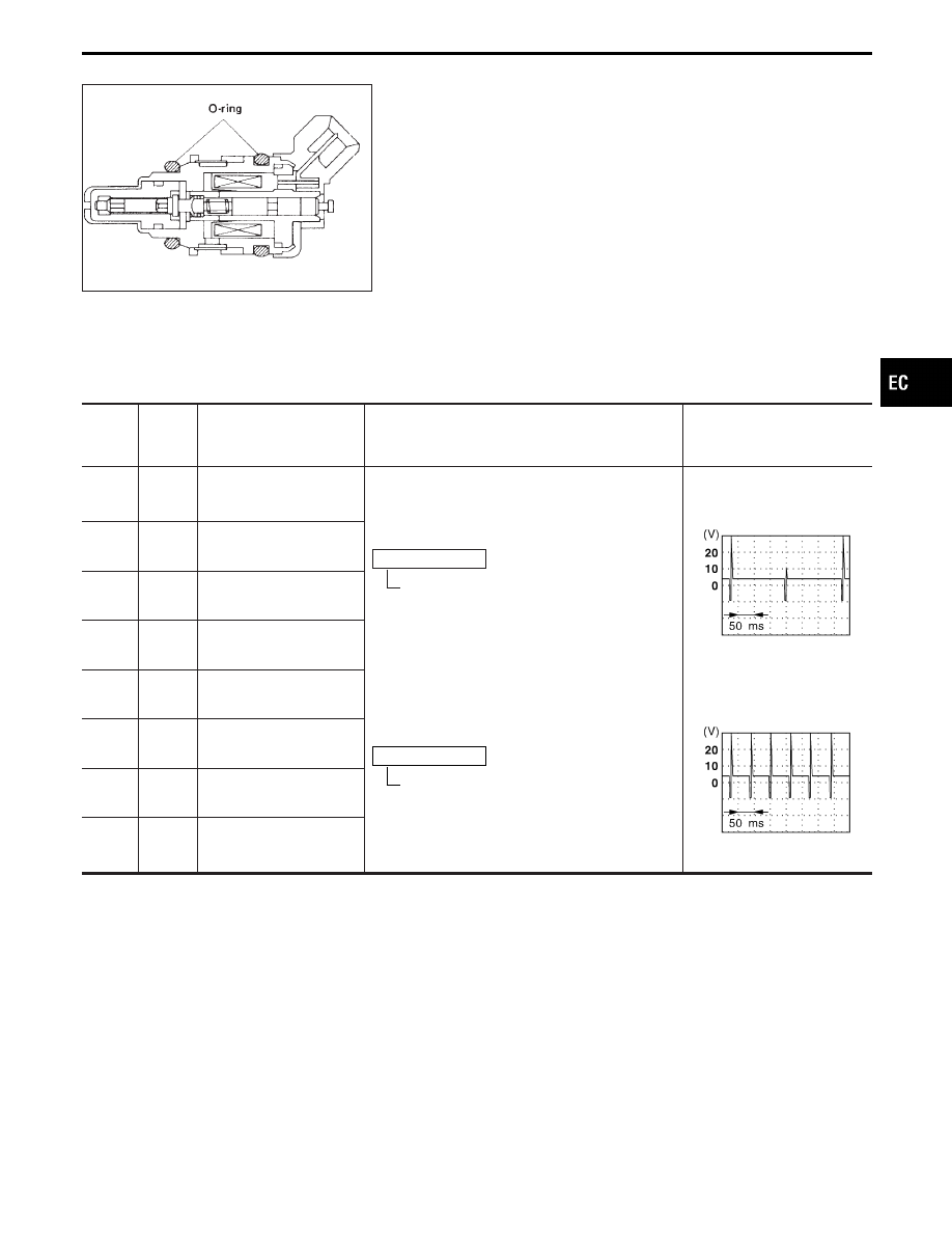
COMPONENT DESCRIPTION
The fuel injector is a small, precise solenoid valve. When the ECM
supplies a ground to the injector circuit, the coil in the injector is
energized. The energized coil pulls the needle valve back and
allows fuel to flow through the injector into the intake manifold. The
amount of fuel injected depends upon the injection pulse duration.
Pulse duration is the length of time the injector remains open. The
ECM controls the injection pulse duration based on engine fuel
needs.
ECM TERMINALS AND REFERENCE VALUE
Specification data are reference values, and are measured between each terminal and ground.
CAUTION:
Do not use ECM ground terminals when measuring voltage. Doing so may result in damage to the
ECM’s transistor. Use a ground other than ECM terminals such as the body ground.
TER-
MINAL
NO.
WIRE
COLOR
ITEM
CONDITION
DATA
(DC voltage)
1
R/B
Injector No. 1
Engine is running. (Warmed-up condition)
Idle speed
BATTERY VOLTAGE
(11 - 14V)
SEF388X
2
R/W
Injector No. 8
3
R/Y
Injector No. 7
14
R/L
Injector No. 3
4
W/R
Injector No. 6
Engine is running.
Engine speed is 2,000 rpm.
BATTERY VOLTAGE
(11 - 14V)
SEF526Y
5
PU/R
Injector No. 5
6
GY/L
Injector No. 4
7
L/G
Injector No. 2
. . . . . . . . . . . . . . . . . . . . . . . . . . . ...
GI
MA
EM
LC
FE
AT
PD
FA
RA
BR
ST
RS
BT
HA
EL
IDX
TROUBLE DIAGNOSIS FOR NON-DETECTABLE ITEMS
Injector (Cont’d)
EC-517
SEF793X
MEC703B
SEF137T
SEF138T
SEF322T
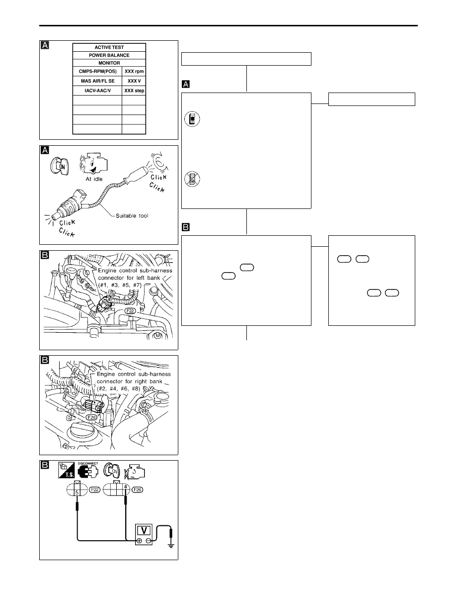
DIAGNOSTIC PROCEDURE
INSPECTION START
CHECK OVERALL FUNCTION.
1. Start engine.
2. Perform “POWER BALANCE” in
“ACTIVE TEST” mode with CON-
SULT-II.
3. Make sure that each circuit pro-
duces a momentary engine
speed drop.
-------------------------------------------------------------------------------------------------------------------------------------- OR --------------------------------------------------------------------------------------------------------------------------------------
2. Listen to each injector operating
sound.
Clicking noise should be
heard.
NG
E
OK
INSPECTION END
CHECK POWER SUPPLY.
1. Stop engine.
2. Disconnect right bank injector sub-har-
ness connectors
F22
and sub-harness
connector
F26
(on the right bank).
3. Turn ignition switch “ON”.
4. Check voltage between terminal
q
4
(right bank),
q
5
(left bank) and ground
with CONSULT-II or tester.
Voltage: Battery voltage
OK
E
NG
Check the following.
I
Harness connectors
F63
,
M49
I
15A fuse
I
Check harness for open
or short between harness
connector
F22
,
F26
and ignition switch.
If NG, repair harness or
connectors.
q
A
(Go to next page.)
TROUBLE DIAGNOSIS FOR NON-DETECTABLE ITEMS
Injector (Cont’d)
H
H
H
EC-518
SEF808W
SEF446U
SEF794T
SEF795T
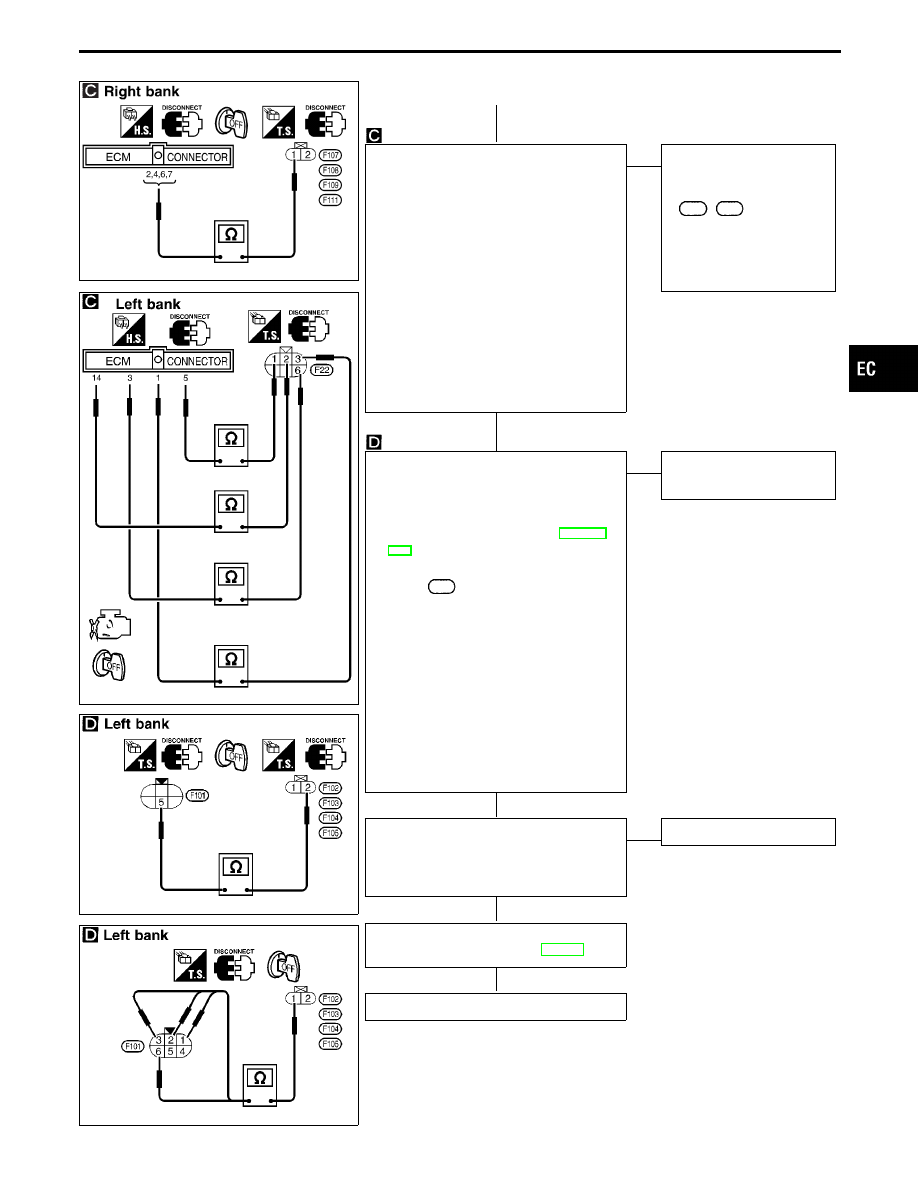
q
A
CHECK OUTPUT SIGNAL CIRCUIT.
1. Turn ignition switch “OFF”.
2. Disconnect ECM harness connector.
3. Check harness continuity between the
following terminals and ECM terminals.
Right bank:
q
1
and
q
2
,
q
4
,
q
6
,
q
7
Left bank:
q
3
and
q
1
,
q
2
and
q
14
,
q
1
and
q
5
,
q
6
and
q
3
Continuity should exist.
If OK, check harness for short to ground
and short to power.
OK
E
NG
Check the following (Right
bank).
I
Harness or connectors
F26
,
F106
If NG, repair open circuit or
short to ground or short to
power in harness or con-
nectors.
CHECK POWER SUPPLY CIRCUIT AND
OUTPUT SIGNAL CIRCUIT (FOR LEFT
BANK).
1. Remove intake manifold collector.
(Refer to “TIMING CHAIN” in EM sec-
tion.)
2. Disconnect injector sub-harness con-
nector
F101
.
3. Check harness continuity between ter-
minal
q
5
and injector terminal
q
2
.
Continuity should exist.
If OK, check harness for short to
ground and short to power.
4. Check harness continuity between
injector terminal
q
1
and terminals
q
3
,
q
2
,
q
1
,
q
6
.
Continuity should exist.
If OK, check harness for short to
ground and short to power.
OK
E
NG
Repair harness or connec-
tors.
CHECK COMPONENT
(Injector).
Refer to “COMPONENT INSPECTION”
on next page.
OK
E
NG
Replace injector.
Perform “TROUBLE DIAGNOSIS FOR
INTERMITTENT INCIDENT”, EC-117.
INSPECTION END
GI
MA
EM
LC
FE
AT
PD
FA
RA
BR
ST
RS
BT
HA
EL
IDX
TROUBLE DIAGNOSIS FOR NON-DETECTABLE ITEMS
Injector (Cont’d)
H
H
H
H
H
EC-519
SEF836Q
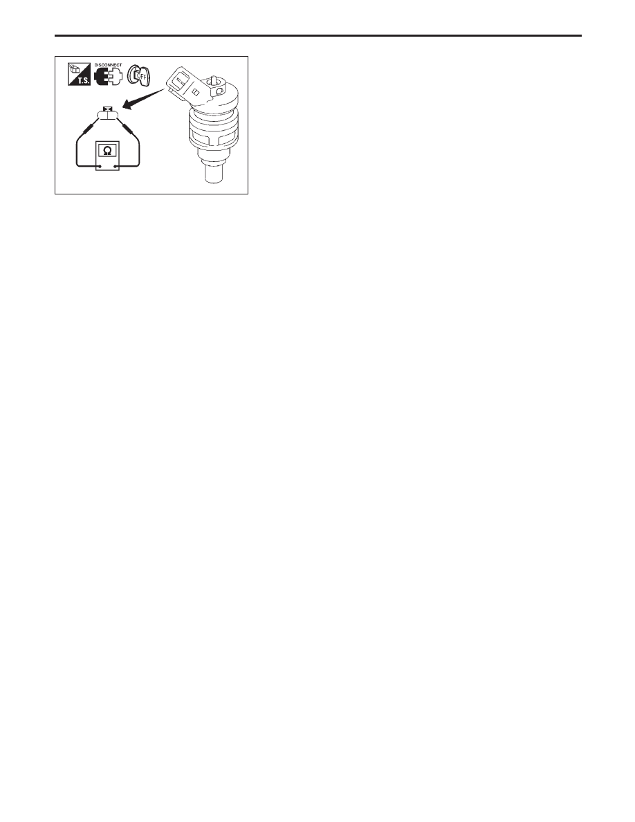
COMPONENT INSPECTION
Injector
1.
Disconnect injector harness connector.
2.
Check resistance between terminals as shown in the figure.
Resistance: 10 - 14
Ω
at 25°C (77°F)
If NG, replace injector.
TROUBLE DIAGNOSIS FOR NON-DETECTABLE ITEMS
Injector (Cont’d)
EC-520
Нет комментариевНе стесняйтесь поделиться с нами вашим ценным мнением.
Текст