Infiniti Q45 (FY33). Manual — part 245
SEF070T
SEF754W
SEF755W
SEF805W
SEF757W
q
A
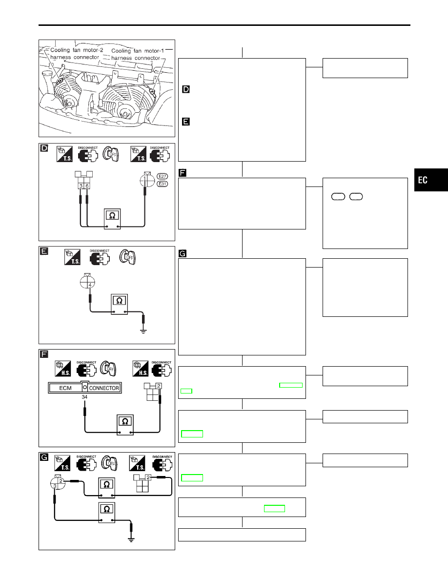
CHECK GROUND CIRCUIT.
1. Turn ignition switch “OFF”.
2. Disconnect cooling fan motor harness
connector.
3. Check harness continuity between
relay terminals
q
3
,
q
6
and cooling
fan motor terminal
q
1
.
Continuity should exist.
If OK, check harness for short.
4. Check harness continuity between
fan motor terminal
q
4
and engine
ground.
Continuity should exist.
If OK, check harness for short to
ground and short to power.
OK
E
NG
Repair harness or connec-
tors.
CHECK OUTPUT SIGNAL CIRCUIT.
1. Disconnect ECM harness connector.
2. Check harness continuity between ECM
terminal
q
34
and relay-2 terminal
q
2
.
Continuity should exist.
If OK, check harness for short to ground
and short to power.
OK
E
NG
Check the following.
I
Harness connectors
F2
,
E13
I
Harness for open or short
between cooling fan
relay-2 and ECM
If NG, repair open circuit or
short to ground or short to
power in harness or con-
nectors.
CHECK HARNESS CONTINUITY
BETWEEN COOLING FAN RELAY-2 AND
GROUND.
1. Turn ignition switch “OFF”.
2. Disconnect cooling fan relay-2.
3. Disconnect triple-pressure switch har-
ness connector.
4. Check harness continuity between
relay-2 terminal
q
2
and switch terminal
q
2
, switch terminal
q
3
and engine
ground.
Continuity should exist.
If OK, check harness for short to ground
and short to power.
OK
E
NG
Check harness for open or
short between triple-pres-
sure switch and relay-2 or
ground.
If NG, repair open circuit or
short to ground or short to
power in harness or con-
nectors.
CHECK COMPONENT
(Triple-pressure switch).
Refer to “Magnet Clutch Circuit” in HA sec-
tion.
OK
E
NG
Replace triple-pressure
switch.
CHECK COMPONENT
(Cooling fan relay-2).
Refer to “COMPONENT INSPECTION”,
EC-514.
OK
E
NG
Replace cooling fan relay.
CHECK COMPONENT
(Cooling fan motors).
Refer to “COMPONENT INSPECTION”,
EC-514.
OK
E
NG
Replace cooling fan motors.
Perform “TROUBLE DIAGNOSIS FOR
INTERMITTENT INCIDENT”, EC-117.
INSPECTION END
GI
MA
EM
LC
FE
AT
PD
FA
RA
BR
ST
RS
BT
HA
EL
IDX
TROUBLE DIAGNOSIS FOR OVERHEAT
Overheat (Cont’d)
H
H
H
H
H
H
H
H
EC-509
SEF160T
SEF407W
SEF758W
SEF070T
SEF759W
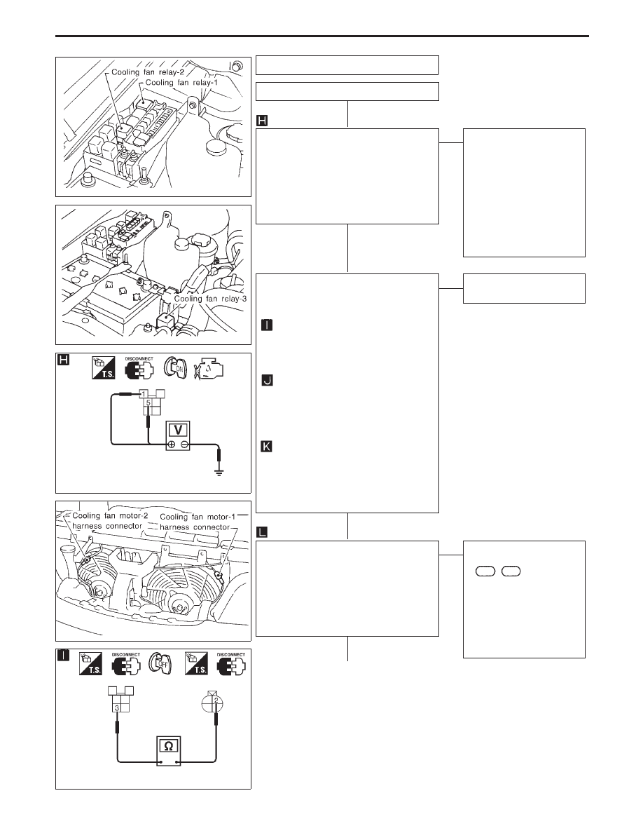
PROCEDURE B
INSPECTION START
CHECK POWER SUPPLY.
1. Turn ignition switch “OFF”.
2. Disconnect cooling fan relay-1 and 3.
3. Turn ignition switch “ON”.
4. Check voltage between cooling fan
relay-1 and -3 terminals
q
1
,
q
5
and
ground with CONSULT-II or tester.
Voltage: Battery voltage
OK
E
NG
Check the following.
I
40A fusible links
I
10A fuse
I
Harness continuity
between cooling fan
relay-1 and -3 and fuse
I
Harness continuity
between cooling fan
relay-1 and -3 and battery
If NG, repair harness or
connectors.
CHECK GROUND CIRCUIT.
1. Turn ignition switch “OFF”.
2. Disconnect cooling fan motor-1 and -2
harness connectors.
3. Check harness continuity between
relay-1 and -3 terminal
q
3
and cool-
ing fan motor-1 and -2 terminal
q
2
.
Continuity should exist.
If OK, check harness for short.
4. Check harness continuity between
relay-1, -3 terminal
q
6
and fan
motor-1 and -2 terminal
q
3
.
Continuity should exist.
If OK, check harness for short to
ground and short to power.
5. Check harness continuity between
relay -1, -3 terminal
q
7
and engine
ground.
Continuity should exist.
If OK, check harness for short to
ground and short to power.
OK
E
NG
Repair harness or connec-
tors.
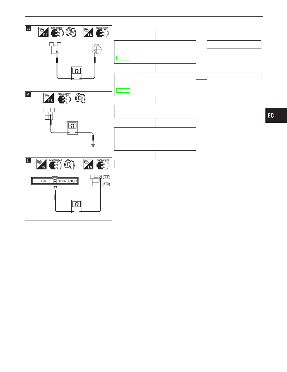
CHECK OUTPUT SIGNAL CIRCUIT.
1. Disconnect ECM harness connector.
2. Check harness continuity between ECM
terminal
q
27
and fan relay-1, -3 terminal
q
2
.
Continuity should exist.
If OK, check harness for short to ground
and short to power.
OK
E
NG
Check the following.
I
Harness connectors
F2
,
E13
I
Harness for open or short
between cooling fan
relay-1, -3 and ECM
If NG, repair open circuit or
short to ground or short to
power in harness or con-
nectors.
q
B
(Go to next page.)
TROUBLE DIAGNOSIS FOR OVERHEAT
Overheat (Cont’d)
H
H
H
H
EC-510
SEF761W
SEF760W
SEF806W
q
B
CHECK COMPONENT
(Cooling fan relay-1 and -3).
Refer to “COMPONENT INSPECTION”,
EC-514.
OK
E
NG
Replace cooling fan relays.
CHECK COMPONENTS
(Cooling fan motors).
Refer to “COMPONENT INSPECTION”,
EC-514.
OK
E
NG
Replace cooling fan motors.
Disconnect and reconnect harness connec-
tors in the circuit. Then retest.
Trouble is not fixed.
Check ECM pin terminals for damage or
the connection of ECM harness connector.
Reconnect ECM harness connector and
retest.
INSPECTION END
GI
MA
EM
LC
FE
AT
PD
FA
RA
BR
ST
RS
BT
HA
EL
IDX
TROUBLE DIAGNOSIS FOR OVERHEAT
Overheat (Cont’d)
H
H
H
H
H
EC-511
SLC754A
SLC755A
SLC343
q
B
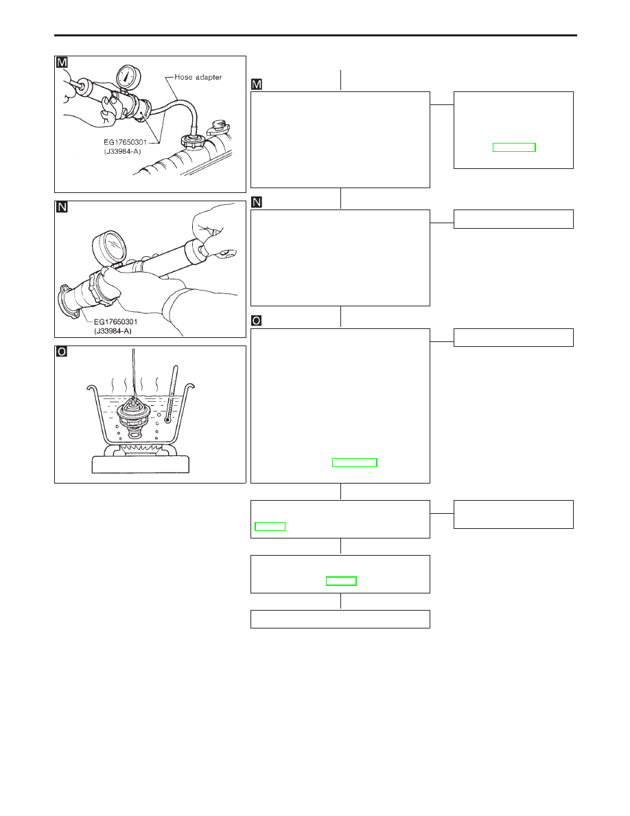
CHECK COOLING SYSTEM FOR LEAK.
Apply pressure to the cooling system with
a tester, and check if the pressure drops.
Testing pressure:
157 kPa (1.6 kg/cm
2
, 23 psi)
Pressure should not drop.
CAUTION:
Higher than the specified pressure may
cause radiator damage.
OK
E
NG
Check the following for
leak.
I
Hose
I
Radiator
I
Water pump
Refer to LC section (“Water
Pump”).
CHECK RADIATOR CAP.
Apply pressure to cap with a tester.
Radiator cap relief pressure:
Standard
98 - 118 kPa (1.0 - 1.2 kg/cm
2
, 14 -
17 psi)
Limit
59 - 118 kPa (0.6 - 1.2 kg/cm
2
, 9 - 17
psi)
OK
E
NG
Replace radiator cap.
CHECK THERMOSTAT.
1. Check valve seating condition at normal
room temperatures.
It should seat tightly.
2. Check valve opening temperature and
maximum valve lift.
Valve opening temperature:
82°C (180°F) [standard]
Maximum valve lift:
More than 8.6 mm/95°C
(0.339 in/203°F)
3. Check if valve is closed at 5°C (9°F)
below valve opening temperature.
For details, refer to LC section (“Thermo-
stat”).
OK
E
NG
Replace thermostat.
Check engine coolant temperature sensor.
Refer to “COMPONENT INSPECTION”,
EC-149.
OK
E
NG
Replace engine coolant
temperature sensor.
If the cause can not be isolated, go to
“MAIN 12 CAUSES OF
OVERHEATING”, EC-513.
INSPECTION END
Perform FINAL CHECK by the following procedure after repair
is completed.
1.
Warn up engine. Run the vehicle for at least 20 minutes. Pay
attention to engine coolant temperature gauge on the instru-
ment panel. If the reading shows an abnormally high
temperature, another part may be malfunctioning.
2.
Stop vehicle and let engine idle. Check the intake and exhaust
systems for leaks by listening for noise or visually inspecting
the components.
3.
Allow engine to cool and visually check for oil and coolant
leaks. Then, perform “OVERALL FUNCTION CHECK”.
TROUBLE DIAGNOSIS FOR OVERHEAT
Overheat (Cont’d)
H
H
H
H
H
H
EC-512
Нет комментариевНе стесняйтесь поделиться с нами вашим ценным мнением.
Текст