Infiniti Q45 (FY33). Manual — part 248
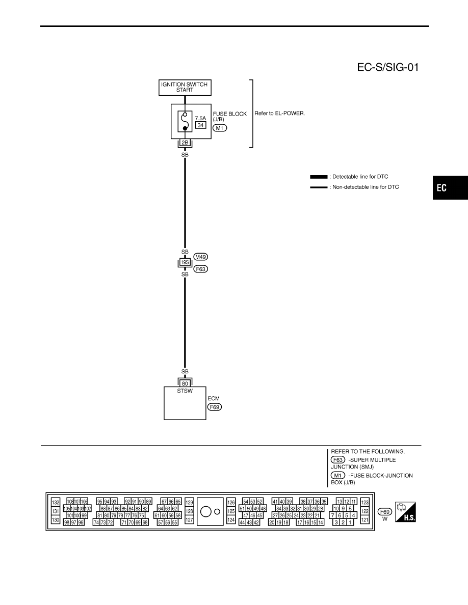
Start Signal
TEC076M
GI
MA
EM
LC
FE
AT
PD
FA
RA
BR
ST
RS
BT
HA
EL
IDX
TROUBLE DIAGNOSIS FOR NON-DETECTABLE ITEMS
EC-521
SEF282Y
SEF449U
SEF450U
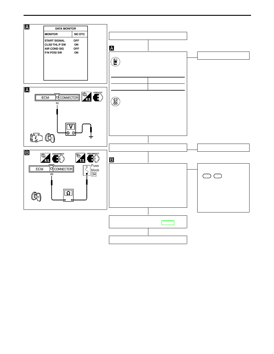
DIAGNOSTIC PROCEDURE
INSPECTION START
CHECK OVERALL FUNCTION.
1. Turn ignition switch “ON”.
2. Check “START SIGNAL” in
“DATA MONITOR” mode with
CONSULT-II.
-------------------------------------------------------------------------------------------------------------------------------------- OR --------------------------------------------------------------------------------------------------------------------------------------
1. Turn ignition switch to “START”.
2. Check voltage between ECM
terminal
q
80
and ground.
Voltage:
Ignition switch “START”
Battery voltage
Except above
Approximately 0V
NG
E
OK
INSPECTION END
Check if 7.5A fuse is OK.
OK
E
NG
Replace 7.5A fuse.
CHECK INPUT SIGNAL CIRCUIT.
1. Turn ignition switch “OFF”.
2. Disconnect ECM harness connector and
7.5A fuse.
3. Check harness continuity between ECM
terminal
q
80
and fuse block.
Continuity should exist.
If OK, check harness for short to ground
and short to power.
OK
E
NG
Check the following.
I
Harness connectors
F63
,
M49
I
Harness for open or short
between ECM and fuse
block
If NG, repair open circuit or
short to ground or short to
power in harness or con-
nectors.
Perform “TROUBLE DIAGNOSIS FOR
INTERMITTENT INCIDENT”, EC-117.
INSPECTION END
IGN “ON”
OFF
IGN “START”
ON
TROUBLE DIAGNOSIS FOR NON-DETECTABLE ITEMS
Start Signal (Cont’d)
H
H
H
H
H
EC-522
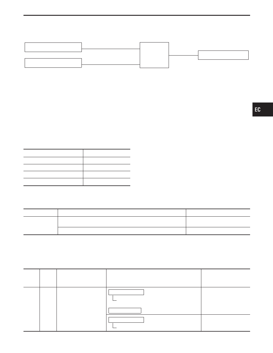
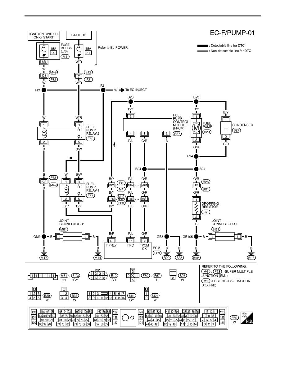
Fuel Pump Control
SYSTEM DESCRIPTION
Camshaft position sensor
E
Engine speed
ECM
E
Fuel pump relay
Ignition switch
E
Start signal
Fuel pump ON-OFF control
The ECM activates the fuel pump for several sec-
onds after the ignition switch is turned ON to
improve engine start-up. If the ECM receives a 1°
signal from the camshaft position sensor, it knows
that the engine is rotating, and causes the pump to
activate. If the 1° signal is not received when the
ignition switch is ON, the engine stalls. The ECM
stops pump operation and prevents the battery from
discharging, thereby improving safety. The ECM
does not directly drive the fuel pump. It controls the
ON/OFF fuel pump relay, which in turn controls the
fuel pump.
Condition
Fuel pump operation
Ignition switch is turned to ON.
Operates for 5 seconds
Engine is running and cranking
Operates
When engine is stopped
Stops for 1.5 seconds
Except as shown above
Stops
CONSULT-II REFERENCE VALUE IN DATA MONITOR MODE
Specification data are reference values.
MONITOR ITEM
CONDITION
SPECIFICATION
FUEL PUMP RLY
I
Ignition switch is turned to ON (Operates for 1 second)
I
Engine running and cranking
ON
Except as shown above
OFF
ECM TERMINALS AND REFERENCE VALUE
Specification data are reference values, and are measured between each terminal and ground.
CAUTION:
Do not use ECM ground terminals when measuring voltage. Doing so may result in damage to the
ECM’s transistor. Use a ground other than ECM terminals such as the body ground.
TER-
MINAL
NO.
WIRE
COLOR
ITEM
CONDITION
DATA
(DC voltage)
11
PU
Fuel pump relay
Ignition switch “ON”
For 5 seconds after turning ignition switch
“ON”
Engine is running.
0 - 1V
Ignition switch “ON”
5 seconds after turning ignition switch “ON”
BATTERY VOLTAGE
(11 - 14V)
GI
MA
EM
LC
FE
AT
PD
FA
RA
BR
ST
RS
BT
HA
EL
IDX
TROUBLE DIAGNOSIS FOR NON-DETECTABLE ITEMS
EC-523
TEC077M
TROUBLE DIAGNOSIS FOR NON-DETECTABLE ITEMS
Fuel Pump Control (Cont’d)
EC-524
Нет комментариевНе стесняйтесь поделиться с нами вашим ценным мнением.
Текст