Infiniti Q45 (FY33). Manual — part 142

Diagnostic Trouble Code (DTC) Inspection
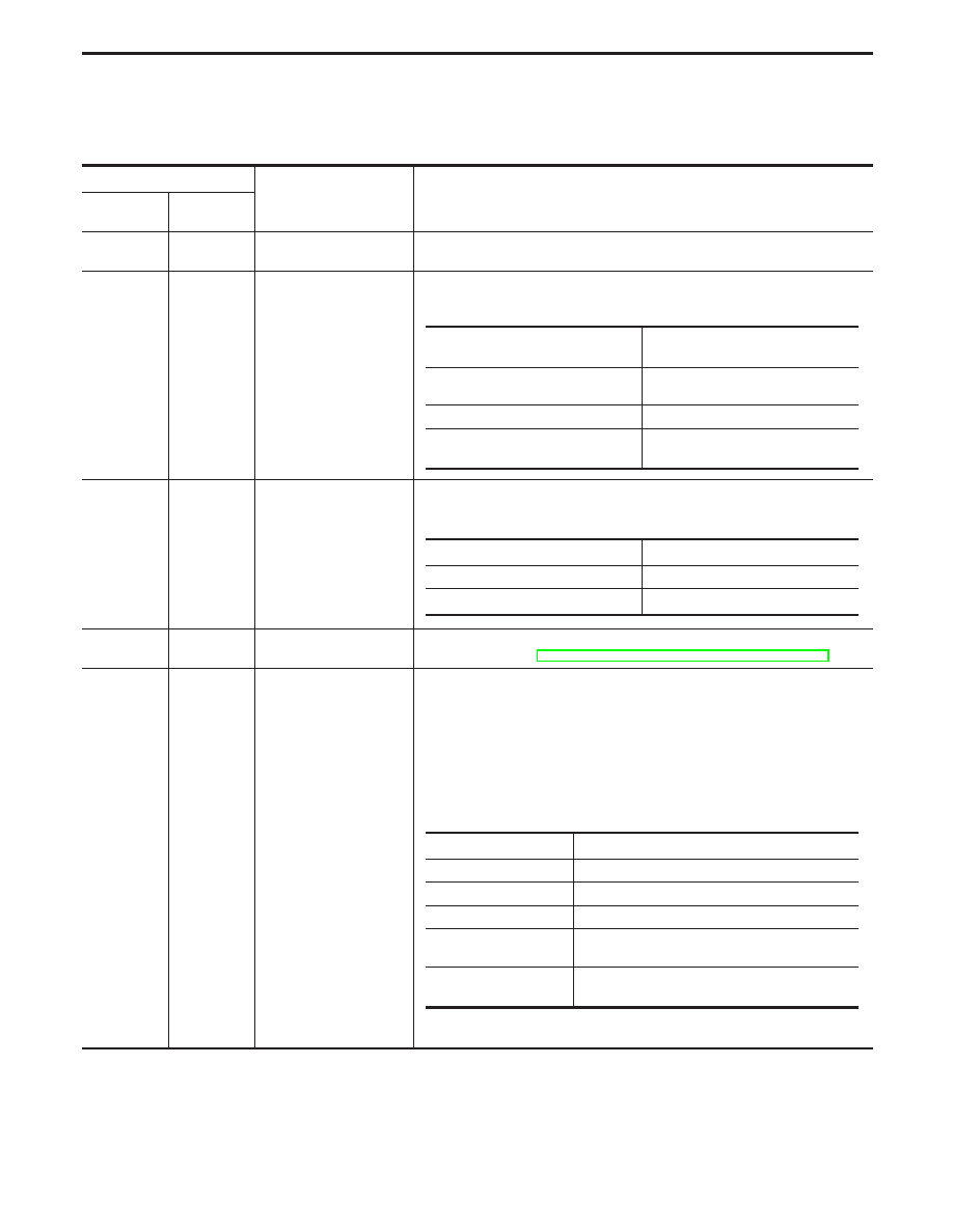
Priority Chart
If some DTCs are displayed at the same time, perform inspections one by one based on the following prior-
ity chart.
Priority
Detected items (DTC)
1
I
ECM (P0605, 0301)
I
Vehicle speed sensor
(P0500, 0104)
I
Engine coolant temperature sensor
(P0115, 0103) (P0125, 0908)
I
Mass air flow sensor
(P0100, 0102)
I
Intake air temperature sensor
(P0110, 0401)
I
Ignition signal circuit (P1320, 0201)
I
Throttle position sensor (P0120,
0403)
I
Knock sensor (P0325, 0304),
(P0330, 0212)
I
Park/Neutral position switch
(P1706, 1003)
I
EGRC-solenoid (P1400, 1005)
I
Crankshaft position sensor (OBD)
circuit (P0335, 0802) (P1336,
0905)
I
Camshaft position sensor (P0340,
0101)
I
A/T communication line (P0600,
0504), (P1605, 0804)
I
Fuel tank temperature sensor
(P0180, 0402)
2
I
EGR temperature sensor (P1401,
0305)
I
Heated oxygen sensors 2 (rear)
(P0137 - P0140) (0150 - 0152,
0707), (P0157 - P0160) (0313 -
0315, 0708)
I
EVAP control system pressure
sensor (P0450, 0704)
I
A/T related sensors, solenoid
valves and switches (P0705 -
P0725, 1101 - 1208) (P0740, 1108
- 1206)
I
Heated oxygen sensors 1 heater
(front) (P0135, 0901) (P0155,
1001)
I
Vacuum cut valve bypass valve
(P1491, 0311) (P1490, 0807)
I
Absolute pressure sensor (P0105,
0803)
I
Closed throttle position switch
(P0510, 0203)
I
EVAP canister vent control valve
(P0446, 0903) (P1446, 0215)
(P1448, 0309)
I
MAP/BARO switch solenoid valve
(P1105, 1302)
I
Intake valve timing control position
sensor circuit (P1140, 1303),
(P1145, 1304)
I
EVAP canister purge volume con-
trol valve (P1444, 0214) (P0443,
1008)
I
Tandem throttle position sensor
(P1125, 0110)
I
Heated oxygen sensors 1 (front)
(P0130 - P0134, 0303, 0409 -
0412) (P0150 - P0154, 0413 -
0415, 0503, 0509)
I
EVAP control system purge flow
monitoring (P1447, 0111)
I
Secondary throttle position sensor
(P1120, 0406)
I
Heated oxygen sensors 2 heater
(rear) (P0141, 0902), (P0161,
1002)
I
EVAP canister purge control valve/
solenoid valve (P1493, 0312),
(P1492, 0807)
3
I
EGR function (P0400, 0302)
(P1402, 0514)
I
TCS signal (P1210, 0106)
I
Fuel pump control module (FPCM)
(P1220, 1305)
I
EVAP control system (SMALL
LEAK) (P0440, 0705) (P1440,
0213) (GROSS LEAK) (P0455,
0715)
I
Misfire (P0300 - P0308, 0701 -
0601)
I
Fuel injection system function
(P0172, 0114), (P0171, 0115),
(P0175, 0209), (P0174, 0210)
I
EGRC-BPT valve function
(P0402, 0306)
I
Closed loop control
(P1148, 0307) (P1168, 0308)
I
Three way catalyst function
(P0420, 0702) (P0430, 0703)
I
IACV-AAC valve
(P0505, 0205)
I
A/T function (P0731 - P0734, 1103
- 1106) (P0744, 1107)
I
Intake valve timing control function
(P1110, 0805), (P1135, 1301)
GI
MA
EM
LC
FE
AT
PD
FA
RA
BR
ST
RS
BT
HA
EL
IDX
TROUBLE DIAGNOSIS — General Description
EC-97
Fail-Safe Chart
The ECM enters fail-safe mode, if any of the following malfunctions are detected due to the open or short cir-
cuit.
When the ECM enters the fail-safe mode, the MIL illuminates.
DTC No.
Detected items
Engine operating condition in fail-safe mode
CONSULT-II
GST
ECM*
P0100
0102
Mass air flow sensor cir-
cuit
Engine speed will not rise more than 2,400 rpm due to the fuel cut.
P0115
0103
Engine coolant tempera-
ture sensor circuit
Engine coolant temperature will be determined by ECM based on the time
after turning ignition switch “ON” or “START”.
CONSULT-II displays the engine coolant temperature decided by ECM.
P0120
0403
Throttle position sensor
circuit
Throttle position will be determined based on the amount of mass air flow
and the engine speed.
Therefore, acceleration will be poor.
P1210
0106
TCS signal circuit
TCS does not operate.
For details, refer to BR section (“TROUBLE DIAGNOSIS FOR TCS”).
Unable to
access ECM
Unable to
access Diag-
nostic Test
Mode II
ECM
ECM fail-safe activating condition
The computing function of the ECM was judged to be malfunctioning.
When the fail-safe system activates, i.e. if the ECM detects a malfunction
condition in the CPU of ECM, the MALFUNCTION INDICATOR LAMP on
the instrument panel lights to warn the driver.
However, it is not possible to access ECM and DTC cannot be confirmed.
Engine control with ECM fail-safe
When the fail-safe system is operating, fuel injection, ignition timing, fuel
pump operation, IACV-AAC valve operation and cooling fan operation are
controlled under certain limitations.
Replace ECM, if ECM fail-safe condition is confirmed.
*: In Diagnostic Test Mode II (Self-diagnostic results)
Condition
Engine coolant temperature decided
(CONSULT-II display)
Just as ignition switch is turned ON or
Start
40°C (104°F)
More than 4 minutes after ignition Start
80°C (176°F)
Except as shown above
40 - 80°C (104 - 176°F)
(Depends on the time)
Driving condition
When engine is idling
Normal
When accelerating
Poor acceleration
ECM fail-safe operation
Engine speed
Engine speed will not rise more than 3,000 rpm.
Fuel injection
Simultaneous multiport fuel injection system
Ignition timing
Ignition timing is fixed at the preset value.
Fuel pump
Fuel pump relay is “ON” when engine is running and
“OFF” when engine stalls.
Cooling fans
Cooling fan relay “ON” (High speed condition) when
engine is running, and “OFF” when engine stalls.
TROUBLE DIAGNOSIS — General Description
EC-98
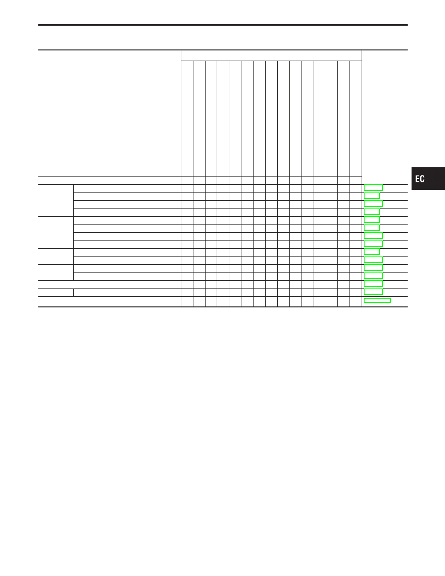
Symptom Matrix Chart
SYSTEM
— Basic engine control system
SYMPTOM
Reference page
HARD/NO
ST
AR
T/REST
AR
T
(EXCP
.
HA)
ENGINE
ST
ALL
HESIT
A
TION/SURGING/FLA
T
SPOT
SP
ARK
KNOCK/DET
ONA
TION
LACK
OF
POWER/POOR
ACCELERA
TION
HIGH
IDLE/LOW
IDLE
ROUGH
IDLE/HUNTING
IDLING
VIBRA
TION
SLOW/NO
RETURN
T
O
IDLE
OVERHEA
TS/W
A
TER
TEMPERA
TURE
HIGH
EXCESSIVE
FUEL
CONSUMPTION
EXCESSIVE
OIL
CONSUMPTION
OVERCOOLS
OVERCHARGING
BA
TTER
Y
DEAD
(UNDER
CHARGE)
Warranty symptom code
AA AB AC AD AE AF AG AH
AJ
AK
AL AM 1P
1X HA
Fuel
Fuel pump circuit
1
1
2
3
2
3
3
3
2
Fuel pressure regulator system
2
3
4
4
4
4
4
4
4
4
Injector circuit
1
1
2
2
2
2
2
2
2
Evaporative emission system
3
3
4
4
4
4
4
4
4
4
Air
Positive crankcase ventilation system
3
3
4
4
4
4
4
4
4
4
1
Incorrect idle speed adjustment
3
3
1
1
1
1
1
IACV-AAC valve circuit
1
1
2
2
2
2
2
2
2
2
IACV-FICD solenoid circuit
3
2
3
3
2
Ignition
Incorrect ignition timing adjustment
3
3
1
1
1
1
1
1
Ignition circuit
1
1
2
3
2
2
3
2
EGR
EGRC-solenoid valve
2
3
3
3
3
3
3
EGR system
2
1
2
3
3
3
2
3
3
3
Main power supply and ground circuit
2
3
3
3
3
2
2
3
3
3
Cooling
Cooling fan circuit
3
3
3
3
3
3
3
3
3
1
2
1
3
Air conditioner circuit
3
3
3
3
3
3
3
3
3
3
3
1 - 6: The numbers refer to the order of inspection.
GI
MA
EM
LC
FE
AT
PD
FA
RA
BR
ST
RS
BT
HA
EL
IDX
TROUBLE DIAGNOSIS — General Description
EC-99
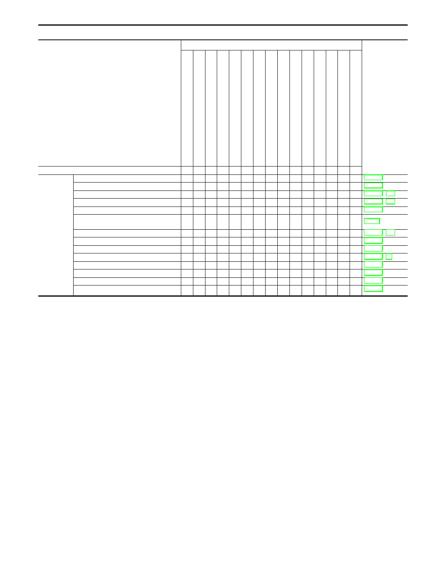
SYSTEM
— Engine control system
SYMPTOM
Reference page
HARD/NO
ST
AR
T/REST
AR
T
(EXCP
.
HA)
ENGINE
ST
ALL
HESIT
A
TION/SURGING/FLA
T
SPOT
SP
ARK
KNOCK/DET
ONA
TION
LACK
OF
POWER/POOR
ACCELERA
TION
HIGH
IDLE/LOW
IDLE
ROUGH
IDLE/HUNTING
IDLING
VIBRA
TION
SLOW/NO
RETURN
T
O
IDLE
OVERHEA
TS/W
A
TER
TEMPERA
TURE
HIGH
EXCESSIVE
FUEL
CONSUMPTION
EXCESSIVE
OIL
CONSUMPTION
OVERCOOLS
OVERCHARGING
BA
TTER
Y
DEAD
(UNDER
CHARGE)
Warranty symptom code
AA AB AC AD AE AF AG AH
AJ
AK
AL AM 1P
1X HA
Engine con-
trol
Camshaft position sensor circuit
2
2
2
2
2
3
3
3
Mass air flow sensor circuit
1
1
2
3
2
2
2
2
2
2
Heated oxygen sensor 1 circuit (front)
2
1
2
3
2
2
3
2
Engine coolant temperature sensor circuit
1
1
3
3
3
3
2
3
3
2
3
Throttle position sensor circuit
1
2
2
3
2
2
3
2
Incorrect throttle position sensor adjust-
ment
2
3
3
1
3
3
1
3
Intake valve timing control system
3
3
3
3
3
Vehicle speed sensor circuit
3
3
3
3
Knock sensor circuit
2
3
2
2
2
3
2
3
ECM
3
3
3
3
3
3
3
3
3
3
3
Start signal circuit
2
Park/Neutral position switch circuit
3
3
3
3
3
FPCM
2
2
2
2
2
Power steering oil pressure switch circuit
2
3
3
1 - 6: The numbers refer to the order of inspection.
TROUBLE DIAGNOSIS — General Description
Symptom Matrix Chart (Cont’d)
EC-100
Нет комментариевНе стесняйтесь поделиться с нами вашим ценным мнением.
Текст