Infiniti Q45 (FY33). Manual — part 140
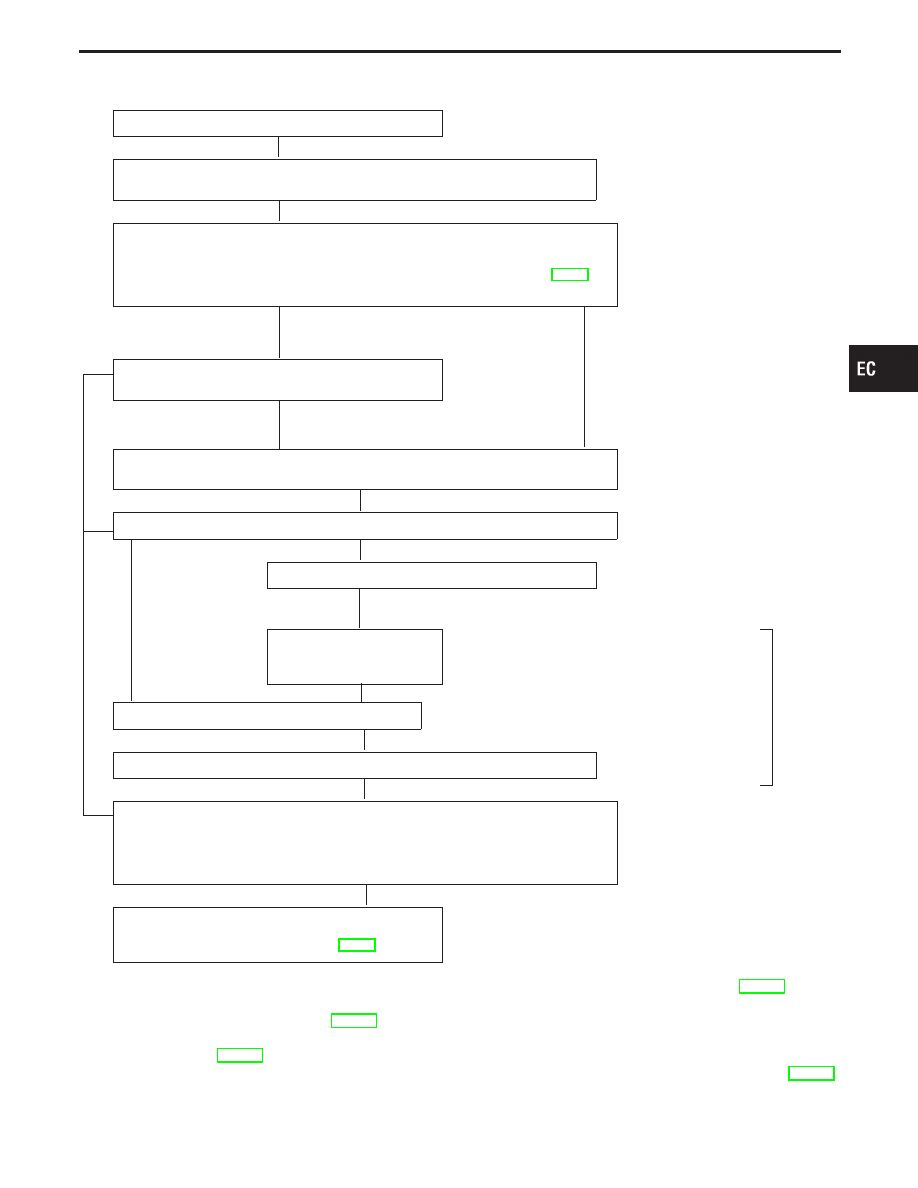
Work Flow
CHECK IN
CHECK INCIDENT CONDITIONS.
Listen to customer complaints. (Get symptoms.)
. . . . . . . . . . . . . STEP I
CHECK DTC and FREEZE FRAME DATA.
Check and PRINT OUT (write down), (1st trip) Diagnostic Trouble Code (DTC) and
Freeze Frame Data (Pre-check). Then clear. Paste it in repair order sheet.
If DTC is not available even if MIL lights up, check ECM fail-safe. (Refer to EC-98.)
Also check related service bulletins for information.
*3
. . . . . . . . . . ... STEP II
Symptoms collected
No symptoms, except MIL
lights up, or (1st trip)
DTC exists at STEP II.
Verify the symptom by driving in the condition the cus-
tomer described.
H
*1
. . . . . . . . . . . . . . . . . . . . . . . . STEP III
Normal Code
(at STEP II)
Malfunction Code
(at STEP II)
INCIDENT INFORMATION
Verify the (1st trip) DTC by performing the “DTC CONFIRMATION PROCEDURE”.
*1
. . . . . . . . . . ... STEP IV
E
Choose the appropriate action.
Malfunction Code (at STEP II or IV)
Normal Code (at both STEP II and IV)
. . . . . . . . . . ...
*2
STEP V
BASIC INSPECTION
SYMPTOM BASIS (at STEP I or III)
. . . . . . . . . . . . . . . ...
E
Perform inspections accord-
ing to Symptom Matrix
Chart.
H
TROUBLE DIAGNOSIS FOR DTC PXXXX.
*4
STEP VI
REPAIR/REPLACE
NG FINAL CHECK
Confirm that the incident is completely fixed by performing BASIC INSPECTION and
DTC CONFIRMATION PROCEDURE (or OVERALL FUNCTION CHECK).
Then, erase the unnecessary (already fixed) DTCs in ECM and TCM (Transmission
Control Module).
OK
. . . . . . . . . . ... STEP VII
CHECK OUT
If completion of SRT is needed, drive the vehicle
under the specific pattern. Refer to EC-56.
*1: If the incident cannot be duplicated, see “TROUBLE DIAGNOSIS FOR INTERMITTENT INCIDENT”, EC-117.
*2: If the on board diagnostic system cannot be performed, check main power supply and ground circuit (See TROUBLE
DIAGNOSIS FOR POWER SUPPLY, EC-118).
*3: If time data of “SELF-DIAG RESULTS” is other than “0” or “1t” refer to “TROUBLE DIAGNOSIS FOR
INTERMITTENT”, EC-117.
*4: If the malfunction part cannot be found, refer to “TROUBLE DIAGNOSIS FOR INTERMITTENT INCIDENT”, EC-117.
GI
MA
EM
LC
FE
AT
PD
FA
RA
BR
ST
RS
BT
HA
EL
IDX
TROUBLE DIAGNOSIS — Work Flow
H
H
H
H
H
H
H
H
H
H
H
EC-89

Description for Work Flow
STEP
DESCRIPTION
STEP I
Get detailed information about the conditions and the environment when the incident/symptom occurred using the
“DIAGNOSTIC WORK SHEET”, EC-87.
STEP II
Before confirming the concern, check and write down (print out using CONSULT-II or Generic Scan Tool) the Diag-
nostic Trouble Code (DTC) and the (1st trip) freeze frame data, then erase the code and the data. (Refer to
EC-63.) The (1st trip) DTC and the (1st trip) freeze frame data can be used when duplicating the incident at STEP
III & IV.
Study the relationship between the cause, specified by (1st trip) DTC, and the symptom described by the customer.
(The “Symptom Matrix Chart” will be useful. See page EC-99.)
Also check related service bulletins for information.
STEP III
Try to confirm the symptom and under what conditions the incident occurs.
The “DIAGNOSTIC WORK SHEET” and the freeze frame data are useful to verify the incident. Connect CON-
SULT-II to the vehicle in DATA MONITOR (AUTO TRIG) mode and check real time diagnosis results.
If the incident cannot be verified, perform INCIDENT SIMULATION TESTS. (Refer to GI section.)
If the malfunction code is detected, skip STEP IV and perform STEP V.
STEP IV
Try to detect the (1st trip) Diagnostic Trouble Code by driving in (or performing) the “DTC CONFIRMATION PRO-
CEDURE”. Check and read the (1st trip) DTC and (1st trip) freeze frame data by using CONSULT-II or Generic
Scan Tool.
During the (1st trip) DTC verification, be sure to connect CONSULT-II to the vehicle in DATA MONITOR (AUTO
TRIG) mode and check real time diagnosis results.
If the incident cannot be verified, perform INCIDENT SIMULATION TESTS. (Refer to GI section.)
In case the “DTC CONFIRMATION PROCEDURE” is not available, perform the “OVERALL FUNCTION CHECK”
instead. The (1st trip) DTC cannot be displayed by this check, however, this simplified “check” is an effective alter-
native.
The “NG” result of the “OVERALL FUNCTION CHECK” is the same as the (1st trip) DTC detection.
STEP V
Take the appropriate action based on the results of STEP I through IV.
If the malfunction code is indicated, proceed to TROUBLE DIAGNOSIS FOR DTC PXXXX.
If the normal code is indicated, proceed to the BASIC INSPECTION on next page. Then perform inspections
according to the Symptom Matrix Chart. (Refer to EC-99.)
STEP VI
Identify where to begin diagnosis based on the relationship study between symptom and possible causes. Inspect
the system for mechanical binding, loose connectors or wiring damage using (tracing) “Harness Layouts”.
Gently shake the related connectors, components or wiring harness with CONSULT-II set in “DATA MONITOR
(AUTO TRIG)” mode.
Check the voltage of the related ECM terminals or monitor the output data from the related sensors with CON-
SULT-II. Refer to EC-102.
The “DIAGNOSTIC PROCEDURE” in EC section contains a description based on open circuit inspection. A short
circuit inspection is also required for the circuit check in the DIAGNOSTIC PROCEDURE. For details, refer to GI
section (“HOW TO PERFORM EFFICIENT DIAGNOSIS FOR AN ELECTRICAL INCIDENT”, “Circuit Inspection”).
Repair or replace the malfunction parts.
STEP VII
Once you have repaired the circuit or replaced a component, you need to run the engine in the same conditions
and circumstances which resulted in the customer’s initial complaint.
Perform the “DTC CONFIRMATION PROCEDURE” and confirm the normal code (Diagnostic trouble code No.
P0000 or 0505) is detected. If the incident is still detected in the final check, perform STEP VI by using a different
method from the previous one.
Before returning the vehicle to the customer, be sure to erase the unnecessary (already fixed) (1st trip) DTC in
ECM and TCM (Transmission Control Module). (Refer to EC-63.)
TROUBLE DIAGNOSIS — Work Flow
EC-90
SEF142I
Basic Inspection
SEF046TA
SEF960X
SEF219U
Precaution:
Perform Basic Inspection without electrical or mechanical
loads applied;
I
Headlamp switch is OFF,
I
Air conditioner switch is OFF,
I
Rear window defogger switch is OFF,
I
Steering wheel is in the straight-ahead position, etc.
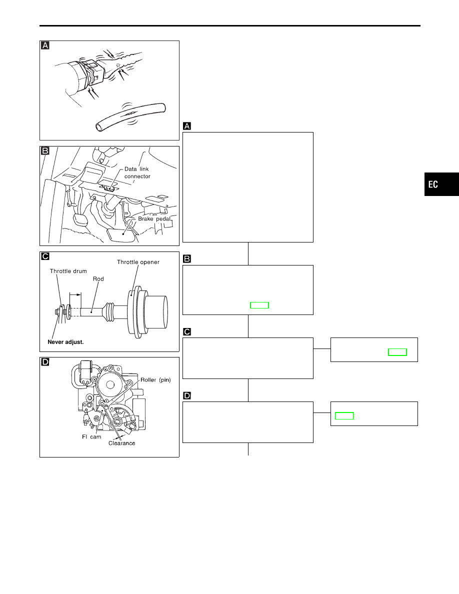
BEFORE STARTING
1. Check service records for recent
repairs of related problems, or the cur-
rent need for scheduled maintenance.
2. Open engine hood and check the fol-
lowing:
I
Harness connectors for improper con-
nections
I
Vacuum hoses for splits, kinks, or
improper connections
I
Wiring for improper connections,
pinches, or cuts
CONNECT CONSULT-II TO THE
VEHICLE.
Connect “CONSULT-II” to the data link
connector and select “ENGINE” from the
menu. (Refer to page EC-74.)
THROTTLE OPENER INSPECTION
1. Start engine and let it idle.
2. Confirm the throttle drum becomes free
from the rod of the throttle opener.
OK
E
NG
Refer to “INSPECTION”,
“Throttle Opener”, EC-39.
CHECK FI CAM.
Warm up engine to normal operating tem-
perature and make sure there is clearance
between FI cam and roller (pin).
OK
E
NG
Check FI cam, refer to
EC-40.
q
A
(Go to next page.)
GI
MA
EM
LC
FE
AT
PD
FA
RA
BR
ST
RS
BT
HA
EL
IDX
TROUBLE DIAGNOSIS — Basic Inspection
H
H
H
H
EC-91
SEF263Y
SEF212U
SEF043T
SEF263Y
SEF115T
q
A
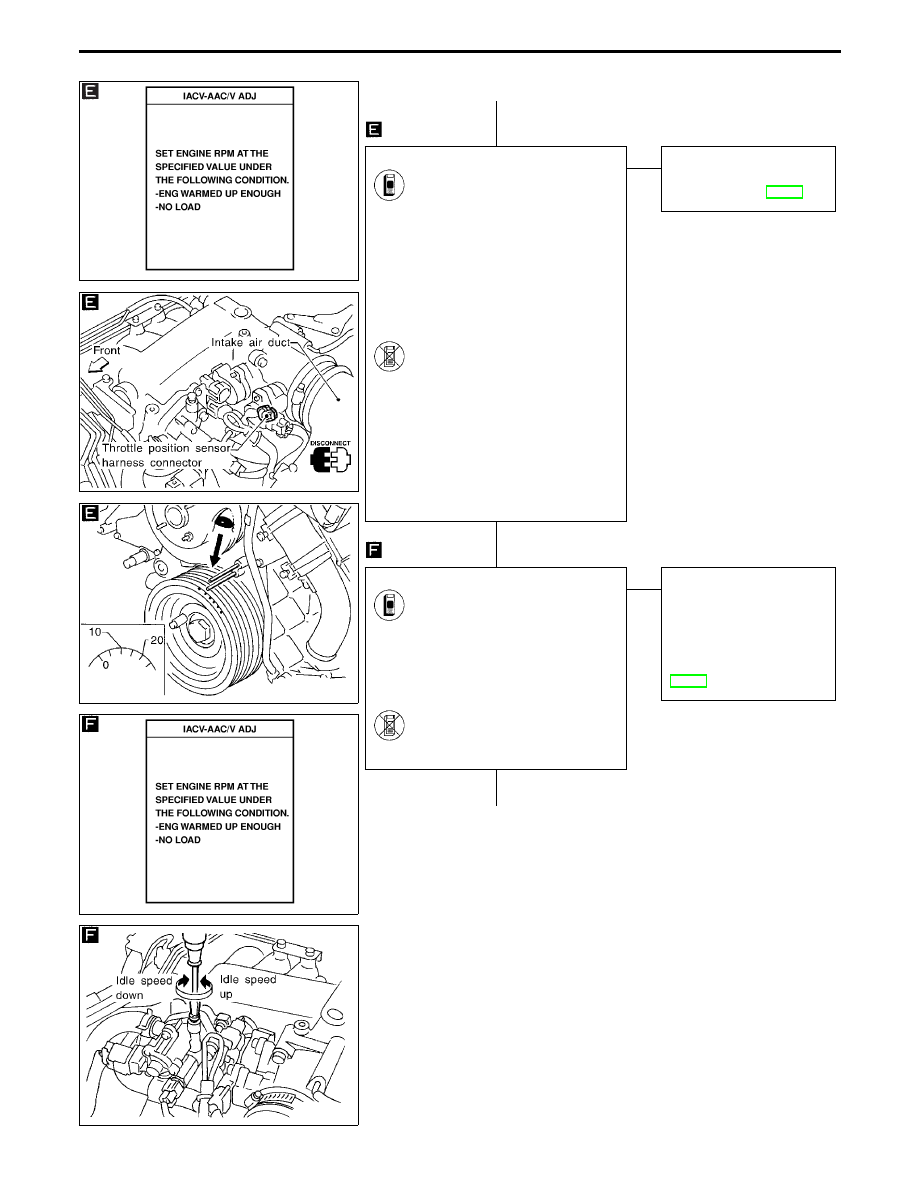
CHECK IGNITION TIMING.
1. Warm up engine to normal
operating temperature.
2. Select “IACV-AAC/V ADJ”
in “WORK SUPPORT” mode.
3. Touch “START”.
4. Check ignition timing at idle
using timing light.
Ignition timing:
15°±2° BTDC
-------------------------------------------------------------------------------------------------------------------------------------- OR --------------------------------------------------------------------------------------------------------------------------------------
1. Warm up engine to normal
operating temperature.
2. Stop engine and disconnect
throttle position sensor harness
connector.
3. Start engine.
4. Check ignition timing at idle
using timing light.
Ignition timing:
15°±2° BTDC
OK
E
NG
Adjust ignition timing by
turning camshaft position
sensor. Refer to EC-42.
CHECK BASE IDLE SPEED.
1. Select “IACV-AAC/V ADJ” in
“WORK SUPPORT” mode.
2. When touching “START”, does
engine speed fall to
600±50 rpm
(in “P” or “N” position)?
-------------------------------------------------------------------------------------------------------------------------------------- OR --------------------------------------------------------------------------------------------------------------------------------------
Does engine run at
600±50 rpm
(in “P” or “N” position)?
OK
E
NG
Adjust base idle speed by
turning idle speed adjust-
ing screw.
Refer to “Idle Speed/
Ignition Timing/Idle Mixture
Ratio Adjustment” in
EC-42.
q
B
(Go to next page.)
TROUBLE DIAGNOSIS — Basic Inspection
Basic Inspection (Cont’d)
H
H
H
EC-92
Нет комментариевНе стесняйтесь поделиться с нами вашим ценным мнением.
Текст