Infiniti Q45 (FY33). Manual — part 143
SYSTEM
— Engine mechanical & other
SYMPTOM
Reference page
HARD/NO
ST
AR
T/REST
AR
T
(EXCP
.
HA)
ENGINE
ST
ALL
HESIT
A
TION/SURGING/FLA
T
SPOT
SP
ARK
KNOCK/DET
ONA
TION
LACK
OF
POWER/POOR
ACCELERA
TION
HIGH
IDLE/LOW
IDLE
ROUGH
IDLE/HUNTING
IDLING
VIBRA
TION
SLOW/NO
RETURN
T
O
IDLE
OVERHEA
TS/W
A
TER
TEMPERA
TURE
HIGH
EXCESSIVE
FUEL
CONSUMPTION
EXCESSIVE
OIL
CONSUMPTION
OVERCOOLS
OVERCHARGING
BA
TTER
Y
DEAD
(UNDER
CHARGE)
Warranty symptom code
AA AB AC AD AE AF AG AH
AJ
AK
AL AM 1P
1X HA
Fuel
Fuel tank
5
5
Fuel piping
2
5
5
2
5
5
5
—
Vapor lock
Valve deposit
5
5
5
5
5
5
5
Poor fuel (Heavy weight gasoline, Low
octane)
Air
Air duct
5
5
5
5
5
5
5
Air cleaner
Air leakage from air duct
(Mass air flow sensor — throttle body)
5
5
5
5
5
Throttle body, Throttle wire
Air leakage from intake manifold/
Collector/Gasket
—
Cranking
Battery
1
1
1
1
1
1
1
1
1
EL section
Alternator circuit
Starter circuit
3
Theft warning circuit
PNP switch
4
Drive plate
6
Engine
Cylinder head
6
6
6
6
6
6
6
6
Cylinder head gasket
4
6
Cylinder block
Piston
Piston ring
Connecting rod
Bearing
Crankshaft
6
Valve
mechanism
Timing chain
6
6
6
6
6
6
6
6
6
Camshaft
5
5
5
5
5
5
5
5
Intake valve
6
6
6
6
6
6
6
6
6
Exhaust valve
Exhaust
Exhaust manifold/Tube/Muffler/Gasket
5
5
5
5
5
5
5
5
Three way catalytic converter
Lubrication
Oil pan/Oil strainer/Oil pump/Oil filter/Oil
gallery
5
5
5
5
5
5
5
5
5
Oil level (Low)/Filthy oil
Cooling
Radiator/Hose/Radiator filler cap
5
5
5
5
5
4
5
Thermostat
5
5
2
Water pump
Water gallery
Cooling fan
5
5
2
EC section
Coolant level (low)/Contaminated coolant
IVIS (Infiniti Vehicle Immobilizer System — NATS)
1
1
EC-69 or EL
section
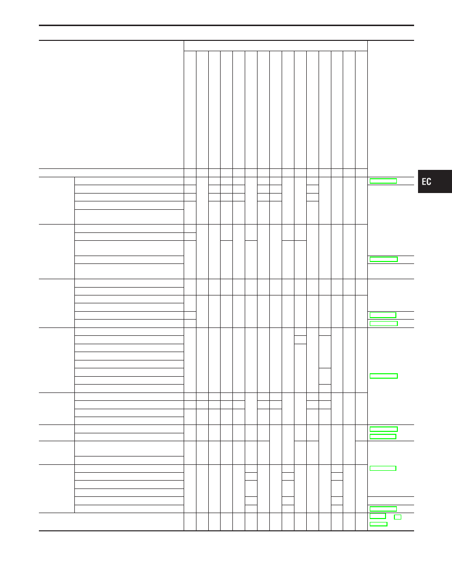
1 - 6: The numbers refer to the order of inspection.
GI
MA
EM
LC
FE
AT
PD
FA
RA
BR
ST
RS
BT
HA
EL
IDX
TROUBLE DIAGNOSIS — General Description
Symptom Matrix Chart (Cont’d)
EC-101
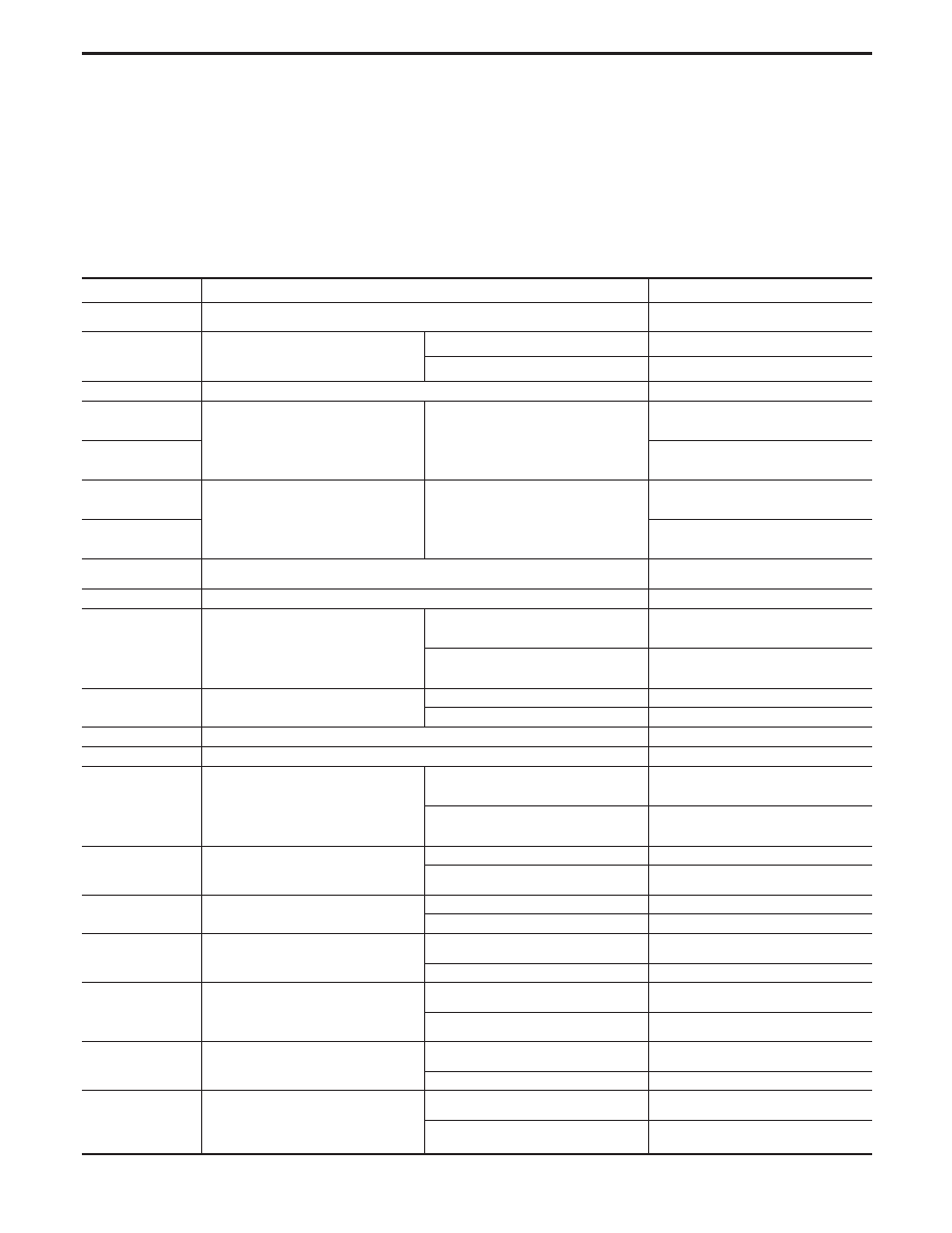
CONSULT-II Reference Value in Data Monitor
Mode
Remarks:
I
Specification data are reference values.
I
Specification data are output/input values which are detected or supplied by the ECM at the connector.
* Specification data may not be directly related to their components signals/values/operations.
i.e. Adjust ignition timing with a timing light before monitoring IGN TIMING, because the monitor may show the specification data
in spite of the ignition timing not being adjusted to the specification data. This IGN TIMING monitors the data calculated by the
ECM according to the signals input from the camshaft position sensor (POS) and other ignition timing related sensors.
I
If the real-time diagnosis results are NG and the on board diagnostic system results are OK when diagnosing the mass air flow
sensor, first check to see if the fuel pump control circuit is normal.
MONITOR ITEM
CONDITION
SPECIFICATION
CMPS
⋅
RPM (POS)
I
Tachometer: Connect
I
Run engine and compare tachometer indication with the CONSULT-II value.
Almost the same speed as the CON-
SULT-II value.
MAS AIR/FL SE
I
Engine: After warming up
I
Air conditioner switch: “OFF”
I
Shift lever: “N”
I
No-load
Idle
1.0 - 1.7V
2,500 rpm
Approx. 2.1V
COOLAN TEMP/S
I
Engine: After warming up
More than 82°C (180°F)
HO2S1 (B1)
. . . . . . . . ..
HO2S1 (B2)
I
Engine: After warming up
Maintaining engine speed at 2,000 rpm
0 - 0.3V
)
0.6 - 1.0V
HO2S1 MNTR (B1)
. . . . . . . . ..
HO2S1 MNTR (B2)
LEAN
)
RICH
Changes more than 5 times
during 10 seconds.
HO2S2 (B1)
. . . . . . . . ..
HO2S2 (B2)
I
Engine: After warming up
Revving engine from idle to 2,000 rpm
quickly
0 - 0.3V
)
0.6 - 1.0V
HO2S2 MNTR (B1)
. . . . . . . . ..
HO2S2 MNTR (B2)
LEAN
)
RICH
VHCL SPEED SE
I
Turn drive wheels and compare speedometer indication with the CONSULT-II
value
Almost the same speed as
the CONSULT-II value
BATTERY VOLT
I
Ignition switch: ON (Engine stopped)
11 - 14V
THRTL POS SEN
I
Engine: After warming up
I
Ignition switch: ON
(Engine stopped)
I
More than −40.0 kPa (−300 mmHg,
−11.81 inHg) of vacuum is applied to
the throttle opener with a handy
vacuum pump.
Throttle valve: fully closed
0.15 - 0.85V
Throttle valve: fully opened
3.5 - 4.7V
THRTL/P SEN2
I
Ignition switch: ON
(Engine stopped)
Throttle valve: fully closed
0.60 - 1.15V
Throttle valve: fully open
4.3 - 4.7V
EGR TEMP SEN
I
Engine: After warming up
Less than 4.5V
START SIGNAL
I
Ignition switch: ON
,
START
,
ON
OFF
,
ON
,
OFF
CLSD THL POS
I
Engine: After warming up
I
Ignition switch: ON
(Engine stopped)
I
More than −40.0 kPa (−300 mmHg,
−11.81 inHg) of vacuum is applied to
the throttle opener with a handy
vacuum pump.
Throttle valve: Idle position
ON
Throttle valve: Slightly open
OFF
AIR COND SIG
I
Engine: After warming up, idle the
engine
Air conditioner switch: “OFF”
OFF
Air conditioner switch: “ON”
(Compressor operates.)
ON
P/N POSI SW
I
Ignition switch: ON
Shift lever: “P” or “N”
ON
Except above
OFF
PW/ST SIGNAL
I
Engine: After warming up, idle the
engine
Steering wheel in neutral position
(forward direction)
OFF
The steering wheel is turned
ON
AMB TEMP SW
I
Engine: Running
Ambient air temperature more than
23.5°C (74°F)
ON
Ambient air temperature less than
20.5°C (69°F)
OFF
LOAD SIGNAL
I
Engine: Running
Rear window defogger or headlamp
“ON”
ON
Except above
OFF
A/C PRESS SW
I
Engine: Running
A/C pressure is more than 1,422 - 1,618
kPa (14.5 - 16.5 kg/cm
2
, 206 - 235 psi)
ON
A/C pressure is less than 1,128 - 1,422
kPa (11.5 - 14.5 kg/cm
2
, 164 - 206 psi)
OFF
Note: B1 indicates Left bank, B2 indicates Right bank.
TROUBLE DIAGNOSIS — General Description
EC-102
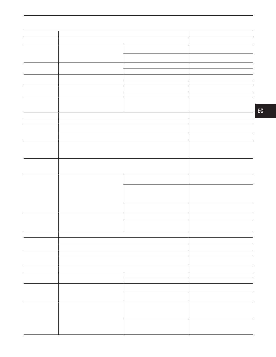
MONITOR ITEM
CONDITION
SPECIFICATION
IGNITION SW
I
Ignition switch: ON
,
OFF
ON
,
OFF
INJ PULSE-B1
. . . . . . . . ..
INJ PULSE-B2
I
Engine: After warming up
I
Air conditioner switch: “OFF”
I
Shift lever: “N”
I
No-load
Idle
2.4 - 3.2 msec.
2,000 rpm
1.9 - 2.8 msec.
B/FUEL SCHDL
ditto
Idle
1.0 - 1.6 msec
2,000 rpm
2.5 - 3.5 msec
IGN TIMING
ditto
Idle
15° BTDC
2,000 rpm
More than 25° BTDC
IACV-AAC/V
ditto
Idle
0 - 10 step
2,000 rpm
—
A/F ALPHA-B1
. . . . . . . . ..
A/F ALPHA-B2
I
Engine: After warming up
Maintaining engine speed at 2,000 rpm
50 - 159%
EVAP SYS PRES
I
Ignition switch: ON
Approx. 3.4V
AIR COND RLY
I
Air conditioner switch:
OFF
,
ON
OFF
,
ON
FUEL PUMP RLY
I
Ignition switch is turned to ON (Operates for 1 second)
I
Engine running and cranking
ON
Except as shown above
OFF
INT/V SOL-B1
. . . . . . . . ..
INT/V SOL-B2
I
Engine is running
I
Engine speed is more than 2,000 rpm
I
Quickly depressed accelerator pedal.
I
Vehicle speed is more than 4 km/h (2 MPH)
OFF
,
ON (Using “INT/V TIM-B1(-2)”,
the difference of degree between “OFF”
and “ON” is approximately 20 deg.)
INT/V TIM-B1
. . . . . . . . ..
INT/V TIM-B2
I
Engine is running
Advanced angle (degree signal) of the
intake camshaft should be displayed.
COOLING FAN
I
After warming up engine, idle the
engine.
I
Air conditioner switch: “OFF”
Engine coolant temperature is 94°C
(201°F) or less
OFF
Engine coolant temperature is between
95°C (203°F) and 104°C (219°F) at
vehicle speed less than 80 km/h (50
MPH)
HIGH
Engine coolant temperature is 105°C
(221°F) or more
HIGH
EGRC SOL/V
I
Engine: After warming up
I
Air conditioner switch: “OFF”
I
Shift lever: “D”
I
No-load
Idle
OFF (Cut)
Revving engine up from idle to 3,000
rpm
ON (Flow)
VENT CONT/V
I
Ignition switch: ON
OFF
HO2S1 HTR (B1)
. . . . . . . . ..
HO2S1 HTR (B2)
I
Engine speed: Idle
ON
I
Engine speed: Above 3,200 rpm
OFF
HO2S2 HTR (B1)
. . . . . . . . ..
HO2S2 HTR (B2)
I
Engine speed: Idle [after driving 2 minutes at 70 km/h (43 MPH) or more]
ON
I
Engine speed: Above 3,600 rpm
I
Ignition switch: ON (Engine stopped)
OFF
VC/V BYPASS/V
I
Ignition switch: ON
OFF
PURG CONT S/V
I
Engine: After warming up
Idle
OFF
2,000 rpm
ON
CAL/LD VALUE
I
Engine: After warming up
I
Air conditioner switch: “OFF”
I
Shift lever: “N”
I
No-load
Idle
13.0 - 32%
2,500 rpm
13.0 - 25.5%
ABSOL TH
⋅
P/S
I
Engine: After warming up
I
Ignition switch: ON
(Engine stopped)
I
More than −40.0 kPa (−300 mmHg,
−11.81 inHg) of vacuum is applied to
the throttle opener with a handy
vacuum pump.
Throttle valve fully closed
0.0%
Throttle valve fully opened
Approx. 88%
GI
MA
EM
LC
FE
AT
PD
FA
RA
BR
ST
RS
BT
HA
EL
IDX
TROUBLE DIAGNOSIS — General Description
CONSULT-II Reference Value in Data Monitor
Mode (Cont’d)
EC-103
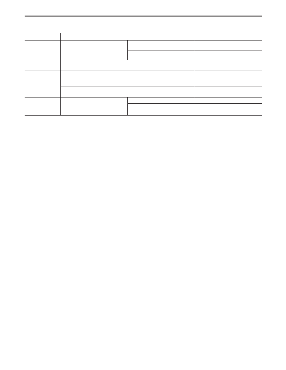
MONITOR ITEM
CONDITION
SPECIFICATION
MASS AIRFLOW
I
Engine: After warming up
I
Air conditioner switch: “OFF”
I
Shift lever: “N”
I
No-load
Idle
3.0 - 6.0 g
⋅
m/s
2,500 rpm
12.9 - 25.3 g
⋅
m/s
FPCM
I
Within 16 seconds after starting engine, when engine coolant temperature is
more than 100°C (212°F)
HIGH
,
LOW
FPCM D/R VOLT
I
Within 16 seconds after starting engine, when engine coolant temperature is
more than 100°C (212°F)
Approx. 5V
,
Approx. 0.4V
MAP/BARO SW/V
I
For 5 seconds after starting engine
BARO
I
More than 5 seconds after turning ignition switch “ON”
I
More than 5 seconds after starting engine
MAP
ABSOL PRES/SE
I
Engine: After warming up
For 5 seconds after starting engine
Approx. 4.4V
More than 5 seconds after starting
engine
Approx. 1.2V
TROUBLE DIAGNOSIS — General Description
CONSULT-II Reference Value in Data Monitor
Mode (Cont’d)
EC-104
Нет комментариевНе стесняйтесь поделиться с нами вашим ценным мнением.
Текст