Infiniti Q45 (FY33). Manual — part 91
SBR366E
q
A
CHECK COMMUNICATION FAILURE
(when cranking engine).
----------------------------------------------------------------------------------------------------------------------------------------------------------------------------------------------------------------------------------------------------------------------------------------------------------------
1. Erase ABS/TCS control unit and TAC
module problem memory.
2. Turn ignition switch to “OFF”, then to
“ON”. (Do not start engine.)
3. Perform self-diagnostic procedures for
TAC module.
4. Does only “THRL POS/S-2 SIG” (self-
diagnostic item) appear on display?
Yes
E
No
q
B
(See next page.)
CHECK COMMUNICATION SYSTEM,
HARNESSES AND CONNECTORS.
----------------------------------------------------------------------------------------------------------------------------------------------------------------------------------------------------------------------------------------------------------------------------------------------------------------
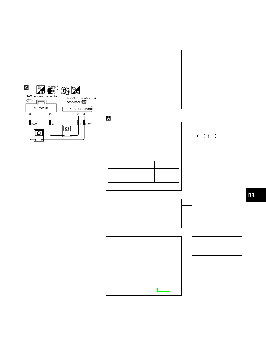
1. Disconnect ABS/TCS control unit and
TAC module connectors.
2. Check continuity between connector
terminals.
Continuity should exist.
OK
E
NG
Check the following.
I
Harness connectors
B103
,
F75
I
Harness for open or
short between TAC mod-
ule connector and ABS/
TCS control unit connec-
tor
If NG, repair harness or
connectors.
Connect connectors, then repeat self-diag-
nostic procedures to ensure that “TAC
module communication” and “THRL POS/
S-2 SIG” appear on display using ABS/
TCS control unit respectively.
Yes
E
No
No items appear on dis-
play. This completes
inspection procedures. If
any other item appears on
display, repair or replace
affected item.
CHECK ABS/TCS CONTROL UNIT
TRANSMISSION CIRCUIT.
----------------------------------------------------------------------------------------------------------------------------------------------------------------------------------------------------------------------------------------------------------------------------------------------------------------
I
Disconnect TAC module connector.
I
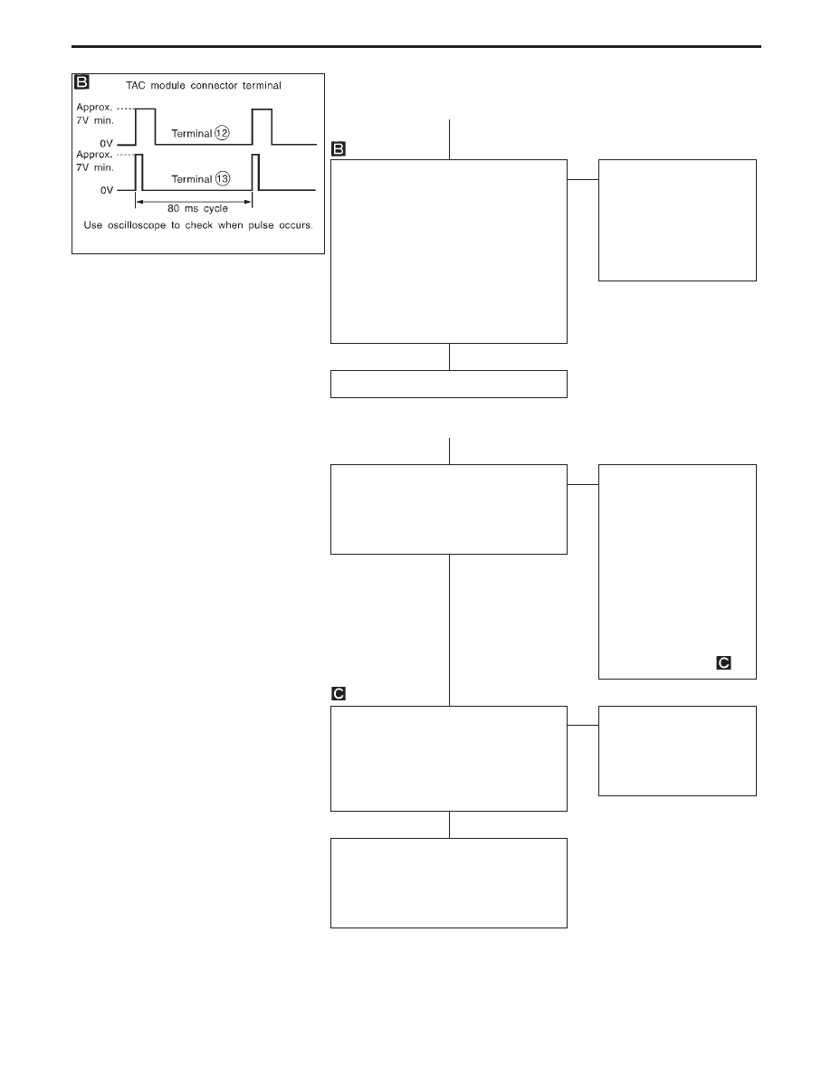
Check waveform pattern and voltage*
between TAC module connector terminal
q
12
and body ground immediately after
turning ignition switch to “ON”.
Waveform pattern and voltage are
indicated in ABS/TCS control unit
inspection table. Refer to BR-123.
OK
E
NG
Faulty ABS/TCS control
unit. (Voltage held to 0V or
7V, min.)
*: Communication output sig-
nal is suspended 5 seconds
after ignition switch is
turned “ON”.
q
C
(Go to next page.)
ABS/TCS control unit
TAC module
q
21
q
13
q
25
q
12
GI
MA
EM
LC
EC
FE
AT
PD
FA
RA
ST
RS
BT
HA
EL
IDX
TROUBLE DIAGNOSES FOR SELF-DIAGNOSTIC ITEMS
Diagnostic Procedure 2 (TCM COMM: TAC
module communication) (Cont’d)
H
H
H
H
H
BR-81
SBR644D
q
C
CHECK ABS/TCS CONTROL UNIT
RECEIVER CIRCUIT AND TAC MODULE
TRANSMITTER-RECEIVER CIRCUITS.
----------------------------------------------------------------------------------------------------------------------------------------------------------------------------------------------------------------------------------------------------------------------------------------------------------------
I
Connect TAC module connector.
I
Turn ignition switch “ON”.
I
Immediately after ignition switch is
turned “ON”, are waveform pattern and
voltage* between TAC module connector
terminals
q
12
,
q
13
and body ground as
shown in the figure at left?
Yes
E
No
Faulty TAC module. (When
pulse output is observed
only at terminal
q
12
and
voltage at terminal
q
13
is
held to 0V or more than
7V, or no pulse output is
observed at terminal
q
12
.)
*: Output signal is suspended
5 seconds after ignition
switch is turned “ON”.
Faulty ABS/TCS control unit.
q
B
I
Start engine. Wait for at least 5
seconds, then perform self-diagnostic
procedures for TAC module. Does
“THRL POS/S-2 SIG” then appear on
display?
Yes
E
No
Immediately after turning
ignition switch “OFF”, re-
start engine and wait for at
least 5 seconds. Perform
self-diagnostic procedures
for TAC module. If “THRL
POS/S-2 SIG” does not
appear on display, ABS/
TCS control unit-TAC mod-
ule communication line is
functioning properly. If
“THRL POS/S-2 SIG”
appears, go to step “
”.
I
Perform self-diagnostic procedures for
TCS/ABS control unit. Ignition switch
must be “ON”.
I
Does indication other than “TCM
COMM” appear under self-diagnostic
items on display?
Yes
E
No
I
Voltage drop while crank-
ing engine.
I
Faulty ABS/TCS control
unit and TAC module
power source system.
Repair or replace affected parts with new
ones. Then, erase trouble codes for ABS/
TCS control unit and/or TAC module from
memory. Start engine and repeat self-di-
agnostic procedures.
TROUBLE DIAGNOSES FOR SELF-DIAGNOSTIC ITEMS
Diagnostic Procedure 2 (TCM COMM: TAC
module communication) (Cont’d)
H
H
H
H
H
BR-82
SBR036EA
Diagnostic Procedure 3 (Engine speed signal)
Code No. 80 of ABS/TCS control unit
SBR368E
Self-diagnostic item “ENGINE SPEED
SIG” appears on display.
1. Perform self-diagnostic procedures for
ECM.
2. Does “CAM POS SEN/CIR”* (self-diag-
nostic item) appear on display?
No
E
Yes
Check ECM.
Refer to EC section,
“TROUBLE DIAGNOSES”.
*: Out of ECM diagnostic
items, only “CAM POS
SEN/CIR” causes TCS to
be suspended (TCS OFF
indicator “ON” and SLIP
indicator “ON”) and allows
ABS/TCS control unit to
indicate “ENGINE SPEED
SIG”.
Perform self-diagnostic procedures for
ECM.
Do “ECM-ABSTCS COMM NG” and “ABS-
TCS C/U SIGNAL”* (self-diagnostic items)
appear on display?
No
E
Yes
Go to diagnostic proce-
dures 4, 5, 6.
Disconnect* ABS/TCS control unit and
ECM connectors, then reconnect them
securely. Repeat self-diagnostic proce-
dures.
NG
E
OK
Poor connector contact.
*: Check for terminal
separation, looseness or
bending, etc., at connector
housing. If necessary, repair
faulty terminals.
CHECK ABS/TCS CONTROL UNIT-TO-
ECM HARNESS CONNECTORS.
----------------------------------------------------------------------------------------------------------------------------------------------------------------------------------------------------------------------------------------------------------------------------------------------------------------
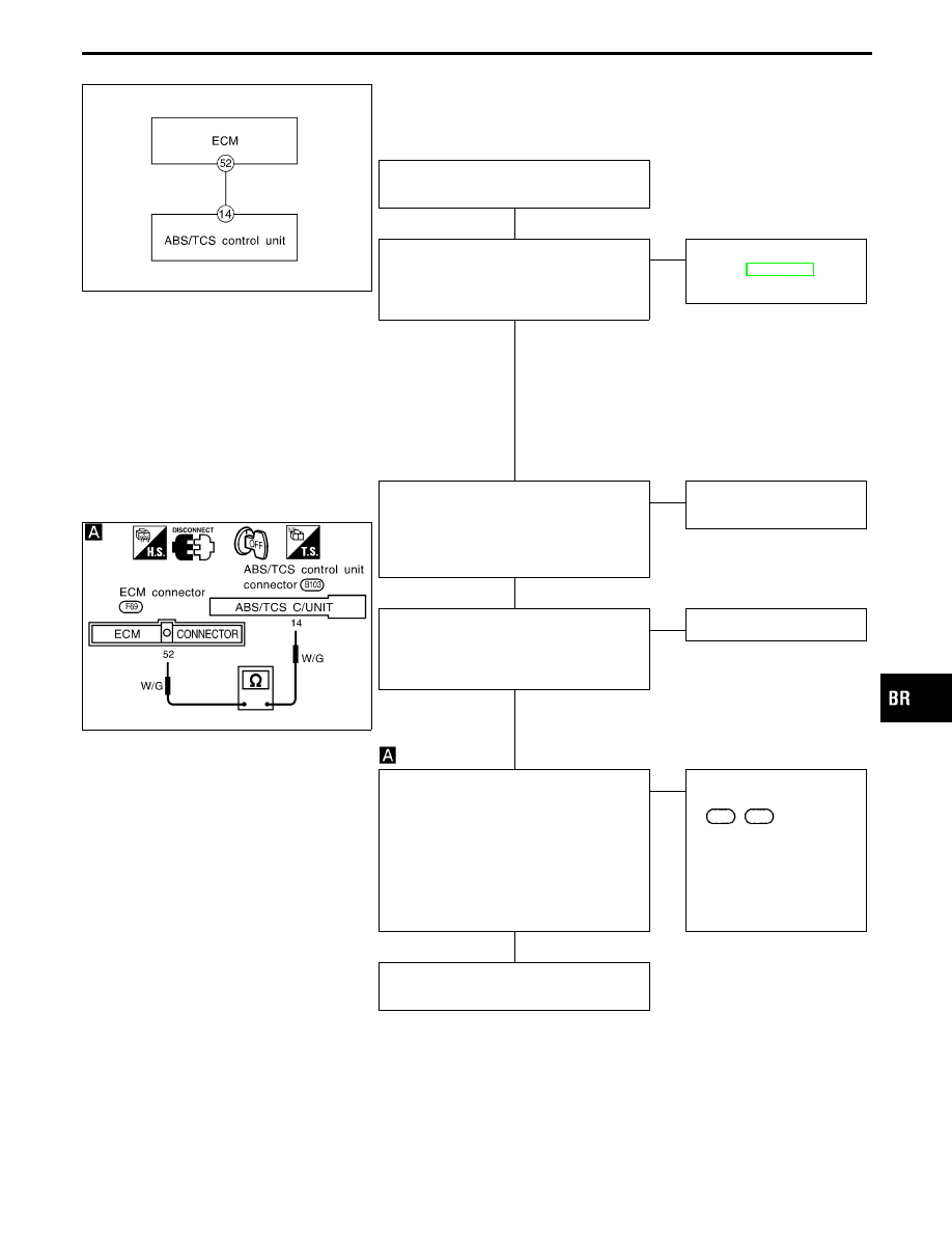
1. Disconnect ABS/TCS control unit and
ECM connectors.
2. Check continuity between terminal
q
14
for ABS/TCS control unit and terminal
q
52
for ECM.
Continuity should exist.
OK
E
NG
Check the following.
I
Harness connectors
F69
,
B103
I
Harness for open or
short between ECM con-
nectors and ABS/TCS
control unit
If NG, repair harness or
connectors.
Connect connectors, then repeat self-diag-
nostic procedures.
GI
MA
EM
LC
EC
FE
AT
PD
FA
RA
ST
RS
BT
HA
EL
IDX
TROUBLE DIAGNOSES FOR SELF-DIAGNOSTIC ITEMS
H
H
H
H
H
BR-83
SBR038EA
Diagnostic Procedure 4 (LAN SIGNAL 1: LAN
monitoring)
Code No. 83 of ABS/TCS control unit
SBR367E
Self-diagnostic item “LAN SIGNAL 1”
appears on display.
Perform self-diagnostic procedures for
ECM.
Does self-diagnostic item “ECM-ABSTCS
COMM NG” appear on display?
No
E
Yes
q
A
(See below.)
Does “ABS-TCS C/U SIGNAL” appear on
display?
Yes
E
No
Faulty ABS/TCS control
unit.
Do any other ABS/TCS control unit self-
diagnostic items appear on display?
No
E
Yes
Repair or replace affected
items shown on display.
Check if battery voltage is too low (less
than 9V) or battery terminals are loose.
OK
E
NG
Repair or replace battery
and power source parts.
Repeat self-diagnostic procedures.
E
NG
Faulty ABS/TCS control
unit.
q
A
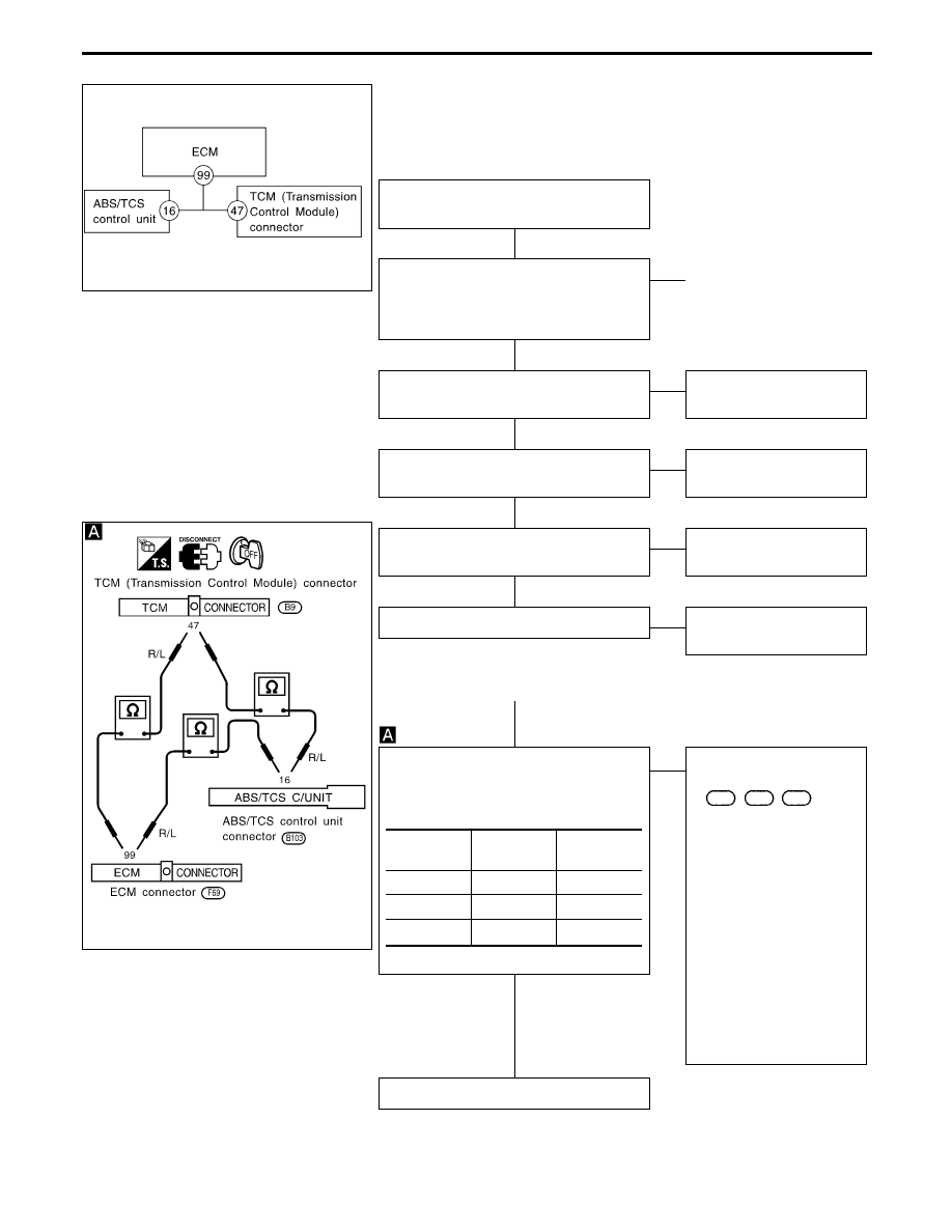
LAN CIRCUIT CHECK
----------------------------------------------------------------------------------------------------------------------------------------------------------------------------------------------------------------------------------------------------------------------------------------------------------------
Check continuity between connector termi-
nals.
Continuity should exist.
OK
E
NG
Check the following.
I
Harness connectors
B103
,
F69
,
B9
I
Harness for open or
short between ECM con-
nector and ABS/TCS
control unit
I
Harness for open or
short between ABS/TCS
control unit connector
and TCM connector
I
Harness for open or
short between ECM con-
nector and TCM connec-
tor
If NG, repair harness or
connectors.
Repeat self-diagnostic procedures.
ABS/TCS
control unit
ECM
TCM
q
16
q
99
q
99
q
47
q
16
q
47
TROUBLE DIAGNOSES FOR SELF-DIAGNOSTIC ITEMS
H
H
H
H
H
H
H
BR-84
Нет комментариевНе стесняйтесь поделиться с нами вашим ценным мнением.
Текст