Infiniti Q45 (FY33). Manual — part 90
SBR576E
SBR640D
GI
MA
EM
LC
EC
FE
AT
PD
FA
RA
ST
RS
BT
HA
EL
IDX
TROUBLE DIAGNOSES
CONSULT-II Inspection Procedure for TAC
Module (Cont’d)
BR-77

DATA MONITOR MODE
Display
Data monitor items
Description
THRTL POS SEN
Throttle position sensor
(V)
I
Displays throttle position sensor signal voltage.
THRTL OPENING
Throttle opening angle
(degree)
I
Displays throttle opening angle calculated from throttle
position sensor signal voltage.
THRTL POS SE2
Secondary throttle position sensor
(V)
I
Displays secondary throttle position sensor signal voltage.
THRL2 OPENING
Secondary throttle valve opening angle
(degree)
I
Displays secondary throttle valve opening angle calcu-
lated from secondary throttle position sensor signal volt-
age.
BATTERY VOLT
Battery voltage
(V)
I
Displays power supply voltage for TCM.
TH OPEN SIG
Throttle opening signal
(ms)
I
Displays pulse width of requesting signal, from TCS con-
trol unit.
CLOSED THL/SW
Closed throttle position switch (ON/OFF)
I
Displays ON/OFF condition determined by throttle position
sensor signal.
NEUT POSI SW
Park/Neutral position switch
(ON/OFF)
I
Displays ON/OFF condition determined by Park/Neutral
position switch signal.
START SIGNAL
Engine start signal
I
Displays ON-OFF condition as determined from START
signal
TH OPEN CONT
Target secondary throttle opening angle
(degree)
I
Displays target secondary throttle valve opening angle
calculated by TCM.
TH MOTOR VOLT
Motor voltage
(V)
I
Displays throttle motor driving voltage.
TH MOTOR DUTY
Motor duty
(%)
I
Displays duty ratio of throttle motor.
TH MOTOR RLY
Motor relay
(ON/OFF)
I
Displays ON/OFF condition of throttle motor relay.
TCS SIGNAL
TCS operation signal
(ON/OFF)
I
Displays ON if secondary throttle valve closes more than
a certain degree.
TCS FLAG
TCS operation flag
I
Displays VALID if TCM controls secondary throttle valve
receiving the requesting signal from TCS control unit.
COMM COND
Communication condition
(ON/OFF)
I
Displays communication condition between TCS control
unit and TCM. Displays ON normally.
TH CLSD LRN
Self-learning
(DONE/YET)
I
Displays self-learning status of fully closed position of sec-
ondary throttle valve by TCM.
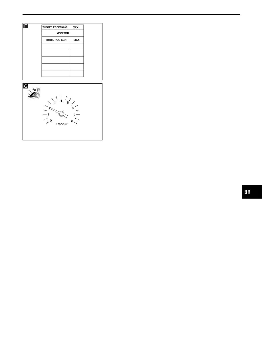
ACTIVE TEST MODE
Display
Active test items
Description
THROTTLE2 OPENING
Secondary throttle valve opening test
I
The target opening angle of secondary throttle valve can
be set manually. The opening angle of secondary throttle
valve and the duty ratio of throttle motor are displayed in
realtime.
THROTTLE MOTOR
Throttle motor operation test
I
The duty ratio of throttle motor can be set manually. The
opening angle of secondary throttle valve is displayed in
realtime.
THROTTLE MOTOR RLY Throttle motor relay test
I
The throttle motor relay can be turned on or off manually
or alternatively.
TROUBLE DIAGNOSES
CONSULT-II Inspection Procedure for TAC
Module (Cont’d)
BR-78
SBR412E
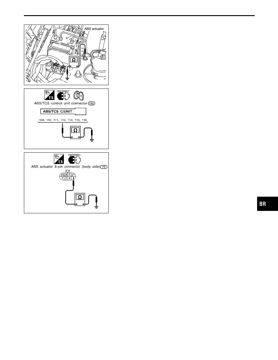
Ground Circuit Check
ABS ACTUATOR MOTOR GROUND
I
Check resistance between actuator motor earth terminal and
body ground.
Resistance: approximately 0
Ω
SBR364E
ABS/TCS CONTROL UNIT GROUND
I
Check resistance between control unit connector terminals and
ground.
Resistance: approximately 0
Ω
SBR365E
ABS ACTUATOR GROUND
I
Check resistance between ABS actuator unit harness 8-pin
connector (body side) terminal
q
21
and ground.
Resistance: approximately 0
Ω
GI
MA
EM
LC
EC
FE
AT
PD
FA
RA
ST
RS
BT
HA
EL
IDX
TROUBLE DIAGNOSES
BR-79
Diagnostic Procedure 1 (Engine system)
Code No. 84 of ABS/TCS control unit
Self-diagnostic item “ENGINE SYSTEM”
appears on display.
1. Perform self-diagnostic procedures for
ECM.
2. Does any of the following self-diagnos-
tic items appear on display?
[CAM POS SEN]*, [MASS AIR FLOW
SEN]*, [COOLANT TEMP SEN]*, [IGN
SIGNAL-PRIMARY]*, [THROTTLE
POSI SEN]*, [TCS THRTL POS SEN]*
No
E
Yes
Go to “TROUBLE DIAG-
NOSES” in EC section.
*: Out of ECM diagnostic
items, 6 items shown at left
cause TCS to be sus-
pended (TCS OFF indicator
“ON” and SLIP indicator
“ON”) and allow ABS/TCS
control unit to indicate
“ENGINE SYSTEM”.
Do “ECM-ABS TCS COMM” and/or “ABS/
TCS C/U SIGNAL” [ECM self-diagnostic
items] appear on display?
No
E
Yes
Perform Diagnostic proce-
dure 4, 5 and 6.
*: Items which cause TCS to
be suspended (TCS OFF
indicator “ON” and SLIP
indicator “ON”) and do not
allow ABS/TCS control unit
to indicate “ENGINE SYS-
TEM”.
If any other diagnostic item appears,
repair or replace affected engine control
system parts.
SBR811D
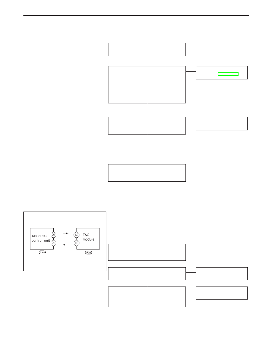
Diagnostic Procedure 2 (TCM COMM: TAC
module communication)
COMMUNICATION LINE BETWEEN ABS/TCS CONTROL
UNIT AND TAC MODULE
Code No. 58 of ABS/TCS control unit
Self-diagnostic item “TCM COMM” (TAC
module communication) appears on dis-
play.
Does only “TAC module communication”
(self-diagnostic item) appear on display?
Yes
E
No
Repair or replace affected
parts.
1. Perform self-diagnostic procedures for
TAC module.
2. Is displayed self-diagnostic item only
“THRL POS/S-2 SIG”?
Yes
E
No
Repair or replace affected
parts.
q
A
(Go to next page.)
TROUBLE DIAGNOSES FOR SELF-DIAGNOSTIC ITEMS
H
H
H
H
H
H
BR-80
Нет комментариевНе стесняйтесь поделиться с нами вашим ценным мнением.
Текст