Infiniti Q45 (FY33). Manual — part 89

SEF046TA
PBR455D
SBR635E
SBR638E
SBR574E
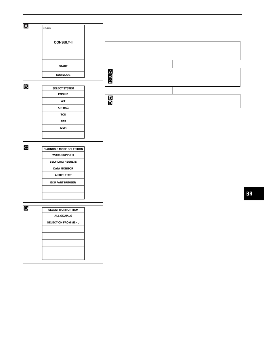
CONSULT-II Inspection Procedure for TAC
Module
SELF-DIAGNOSIS PROCEDURE
1) Turn ignition switch OFF.
2) Connect CONSULT-II to Data Link Con-
nector.
1) Start engine.
2) Drive vehicle over 30 km/h (19 MPH)
for at least one minute.
1) Stop vehicle with engine running
and touch “START” on CON-
SULT-II screen.
2) Touch “TCS”.
3) Touch “SELF-DIAG
RESULTS”.
I
Does the screen show the detected
malfunction?
Yes
E
No
SLIP INDICATOR, TCS
OFF INDICATOR
INSPECTION
---------------------------------------------------------------------------------------------------------------------------------------------------------------------------------------------------------
Check SLIP indicator, TCS
OFF indicator and the cir-
cuit and repair if neces-
sary.
MALFUNCTION REPAIR
----------------------------------------------------------------------------------------------------------------------------------------------------------------------------------------------------------------------------------------------------------------------------------------------------------------
Make the necessary repairs following the
diagnostic procedures.
Start engine and drive vehicle at 30 km/h
(19 MPH) or more for more than one
minute.
Turn ignition switch “OFF” so self-diagnos-
tic system is ready for memory erasure.
After repairing the malfunctions, start
engine. Then erase the self-diagnostic
results stored in the control unit by touch-
ing “ERASE”.
Are the self-diagnostic results erased?
Yes
E
No
Go to MALFUNCTION
REPAIR.
Check SLIP indicator and TCS OFF indi-
cator for deactivation after driving vehicle
over 30 km/h (19 MPH) for at least one
minute.
Do the SLIP indicator and TCS OFF
indicator activate?
No
E
Yes
Go to
above.
End
Note: “SELF-DIAG RESULTS” screen shows the detected malfunction and
the times of ignition switch ON and OFF after it occurred.
GI
MA
EM
LC
EC
FE
AT
PD
FA
RA
ST
RS
BT
HA
EL
IDX
TROUBLE DIAGNOSES
H
H
H
H
H
H
H
H
BR-73

SELF-DIAGNOSTIC RESULTS MODE
Display
Self-diagnostic items
Malfunction is detected when ...
Diagnostic
procedure
THROTTLE POSI SEN
Throttle position sensor cir-
cuit
I
The throttle position sensor circuit is open or
shorted.
(An abnormally high or low voltage is
entered.)
14
THROTTLE POSI SEN2
Secondary throttle position
sensor circuit
I
The secondary throttle position sensor circuit
is open or shorted.
(An abnormally high or low voltage is
entered.)
15
THRTL POS/S-2 SIG
Secondary throttle valve
operating signal circuit
I
TCS control unit is in fail-safe condition or
harness is abnormal.
I
Faulty ABS/TCS control unit
16
THROTTLE ACTUATOR
Throttle motor circuit (Opera-
tion and open circuit check)
I
The throttle motor does not operate normally
when the TCS is operating.
17
THROTTLE MOTOR
Throttle motor circuit (Short
circuit check)
I
The throttle motor circuit is shorted.
17
THROTTLE MOTOR RLY
[SHORT] (
⋅
a)
Throttle motor relay circuit
(Short)
I
The throttle motor relay is shorted.
18
THROTTLE MOTOR RLY
[OPEN] (
⋅
b)
Throttle motor relay circuit
(Open)
I
The throttle motor relay is open.
18
THRTL/V RETURN SPR
Secondary throttle valve
return spring broken
I
Secondary throttle valve does not fully open
when current is not supplied to the motor.
20
ENGINE START SIG
Engine start signal circuit
I
START signal is not properly input due to
short-circuit.
21
NEUTRAL POSI SW
Park/Neutral position switch
circuit
I
Park/Neutral position switch circuit is open.
I
Park/Neutral position switch circuit is shorted.
22
TH P/S PWR SUPPLY
Power supply circuit
(for sensor)
I
Power supply circuit for secondary throttle
position sensor is open.
19
NOTE:
Appears on display when self-diagnosis is performed with self-diagnostic check terminal (terminal No.
9 of data link connector) shorted to ground.
TROUBLE DIAGNOSES
CONSULT-II Inspection Procedure for TAC
Module (Cont’d)
BR-74
PBR455D
DATA MONITOR PROCEDURE
SBR635E
SBR640E
SBR571E
1) Turn ignition switch OFF.
2) Connect CONSULT-II to Data Link Connector.
3) Turn ignition switch ON.
1) Touch “START” on CONSULT-II screen.
2) Touch “TCS”.
3) Touch “DATA MONITOR”.
1) Touch “SETTING” on “SELECT MONITOR ITEM” screen.
2) Touch “START” on “SELECT MONITOR ITEM”.
GI
MA
EM
LC
EC
FE
AT
PD
FA
RA
ST
RS
BT
HA
EL
IDX
TROUBLE DIAGNOSES
CONSULT-II Inspection Procedure for TAC
Module (Cont’d)
H
H
BR-75

PBR455D
ACTIVE TEST PROCEDURE
I
When conducting Active test, vehicle must be stationary.
SBR635E
SBR636E
SBR575E
SBR639E
1) Turn ignition switch OFF.
2) Connect CONSULT-II to Data Link Connector.
3) Start engine.
1) Touch “START” on CONSULT-II screen.
2) Touch “TCS”.
3) Touch “ACTIVE TEST”.
1) Select active test item by touching screen.
2) Touch “START”.
1) Set motor throttle target position to “0°” (throttle fully closed).
Approx. “2°” (motor throttle position) will appear on CONSULT-II display.
1) Following motor throttle target position setting, depress accelerator
pedal to ensure that engine speed is limited.
2) Ensure that engine speed is limited in response to different throttle posi-
tions.
TROUBLE DIAGNOSES
CONSULT-II Inspection Procedure for TAC
Module (Cont’d)
H
H
H
H
BR-76
Нет комментариевНе стесняйтесь поделиться с нами вашим ценным мнением.
Текст