Infiniti M35/M45 Y50. Manual — part 878

HEADLAMP (FOR USA) - XENON TYPE -
LT-57
C
D
E
F
G
H
I
J
L
M
A
B
LT
3.
CHECK GROUND CIRCUIT
Check continuity between BCM harness connector and ground.
OK or NG
OK
>> INSPECTION END
NG
>> Repair harness or connector.
CONSULT-II Functions (BCM)
NKS003OU
CONSULT-II can display each diagnostic item using the diagnostic test mode shown following.
NOTE:
Cannot change the setting for headlamp.
CONSULT-II BASIC OPERATION
Refer to
GI-38, "CONSULT-II Start Procedure"
.
DATA MONITOR
Operation Procedure
1.
Touch “HEAD LAMP” on “SELECT TEST ITEM” screen.
2.
Touch “DATA MONITOR” on “SELECT DIAG MODE” screen.
3.
Touch either “ALL SIGNALS” or “SELECTION FROM MENU” on the “SELECT MONITOR ITEM” screen.
4.
When “SELECTION FROM MENU” is selected, touch individual items to be monitored. When “ALL SIG-
NALS” is selected, all the items will be monitored.
5.
Touch “START”.
6.
Touch “RECORD” while monitoring, then the status of the monitored item can be recorded. To stop
recording, touch “STOP”.
Display Item List
BCM connector
Terminal
Ground
Continuity
M2
52
Yes
SKIB5125E
BCM diagnosis part
Diagnosis mode
Description
HEADLAMP
WORK SUPPORT
Changes the setting for each function.
NOTE
DATA MONITOR
Displays BCM input data in real time.
ACTIVE TEST
Operation of electrical loads can be checked by sending drive signal to them.
BCM
SELF-DIAG RESULTS
BCM performs self-diagnosis of CAN communication.
CAN DIAG SUPPORT MNTR
The result of transmit/receive diagnosis of CAN communication can be read.
ALL SIGNALS
Monitors all the signals.
SELECTION FROM MENU
Selects items and monitor them.
Monitor item
Contents
IGN ON SW
“ON/OFF”
Displays “IGN position (ON)/OFF, ACC position (OFF)” judged from the ignition switch signal.
ACC ON SW
“ON/OFF”
Displays “ACC (ON)/OFF, Ignition OFF (OFF)” status judged from ignition switch signal.
KEY ON SW
“ON/OFF”
Displays “Intelligent Key inserted into key slot (ON)/Intelligent Key removed from key slot
(OFF)” status judged from the key switch signal.
TURN SIGNAL R
“ON/OFF”
Displays status (turn right: ON/others: OFF) as judged from lighting switch signal.
TURN SIGNAL L
“ON/OFF”
Displays status (turn left: ON/others: OFF) as judged from lighting switch signal.
HI BEAM SW
“ON/OFF”
Displays status (high beam switch: ON/others: OFF) of high beam switch judged from lighting
switch signal.

LT-58
HEADLAMP (FOR USA) - XENON TYPE -
NOTE:
This item is displayed, but cannot be monitored.
ACTIVE TEST
Operation Procedure
1.
Touch “HEAD LAMP” on “SELECT TEST ITEM” screen.
2.
Touch “ACTIVE TEST” on “SELECT DIAG MODE” screen.
3.
Touch item to be tested and check operation of the selected item.
4.
During the operation check, touching “BACK” deactivates the operation.
Display Item List
NOTE:
This item is displayed, but cannot be tested.
HEAD LAMP SW 1
“ON/OFF”
Displays status (headlamp switch 1: ON/others: OFF) of headlamp switch 1 judged from light-
ing switch signal.
HEAD LAMP SW 2
“ON/OFF”
Displays status (headlamp switch 2: ON/others: OFF) of headlamp switch 2 judged from light-
ing switch signal.
TAIL LAMP SW
“ON/OFF”
Displays status (lighting switch 1ST or 2ND position: ON/others: OFF) of lighting switch
judged from lighting switch signal.
AUTO LIGHT SW
“ON/OFF”
Displays status of the lighting switch as judged from the lighting switch signal. (AUTO position:
ON/other than AUTO position: OFF)
PASSING SW
“ON/OFF”
Displays status (flash-to-passing switch: ON/others: OFF) of flash-to-passing switch judged
from lighting switch signal.
FR FOG SW
“ON/OFF”
Displays status (front fog lamp switch: ON/others: OFF) of front fog lamp switch judged from
lighting switch signal.
DOOR SW - DR
“ON/OFF”
Displays status of the driver door as judged from the driver door switch signal. (door is open:
ON/door is closed: OFF)
DOOR SW - AS
“ON/OFF”
Displays status of the passenger door as judged from the passenger door switch signal. (door
is open: ON/door is closed: OFF)
DOOR SW - RR
“ON/OFF”
Displays status of the rear door as judged from the rear door switch (RH) signal. (door is
open: ON/door is closed: OFF)
DOOR SW - RL
“ON/OFF”
Displays status of the rear door as judged from the rear door switch (LH) signal. (door is open:
ON/door is closed: OFF)
BACK DOOR SW
NOTE
“OFF”
—
I - KEY LOCK
“ON/OFF”
Displays “locked (ON)/other (OFF)” status, determined from lock signal.
OPTICAL SENSOR
“0 - 5V”
Displays “outside brightness (close to 5 V when light/close to 0 V when dark)” judged from
optical sensor signal.
VEHICLE SPEED
“km/h”
Displays vehicle speed as judged from vehicle speed signal.
Monitor item
Contents
Test item
Description
TAIL LAMP
Allows tail lamp relay to operate by switching ON-OFF.
FR FOG LAMP
Allows front fog lamp relay to operate by switching ON-OFF.
DAYTIME RUNNING LIGHT
NOTE
—
HEAD LAMP (HI, LO)
Allows headlamp relay to operate by switching ON-OFF.

HEADLAMP (FOR USA) - XENON TYPE -
LT-59
C
D
E
F
G
H
I
J
L
M
A
B
LT
CONSULT-II Functions (IPDM E/R)
NKS003OV
CONSULT-II can display each diagnostic item using the diagnostic test mode shown following.
CONSULT-II BASIC OPERATION
Refer to
GI-38, "CONSULT-II Start Procedure"
.
DATA MONITOR
Operation Procedure
1.
Touch “DATA MONITOR” on “SELECTION DIAG MODE ” screen.
2.
Touch “ALL SIGNALS”, “MAIN SIGNALS” or “SELECTION FROM MENU” on the “SELECT MONITOR
ITEM” screen.
3.
When “SELECTION FROM MENU” is selected, touch individual items to be monitored. In “ALL SIG-
NALS”, all items are monitored. In “MAIN SIGNALS”, predetermined items are monitored.
4.
Touch “START”.
5.
Touch “RECORD” while monitoring to record the status of the item being monitored. To stop recording,
touch “STOP”.
All Signals, Main Signals, Selection From Menu
NOTE:
Perform monitoring of IPDM E/R data with the ignition switch ON. When the ignition switch is at ACC, the display may not be correct.
ACTIVE TEST
Operation Procedure
1.
Touch “ACTIVE TEST” on “SELECT DIAG MODE” screen.
2.
Touch item to be tested, and check operation.
3.
Touch “START”.
4.
Touch “STOP” while testing to stop the operation.
Diagnosis Mode
Description
SELF-DIAGNOSTIC RESULTS
Refer to
DATA MONITOR
The input/output data of IPDM E/R is displayed in real time.
CAN DIAG SUPPORT MNTR
The result of transmit/receive diagnosis of CAN communication can be read.
ACTIVE TEST
IPDM E/R sends a drive signal to electronic components to check their operation.
ALL SIGNALS
Monitors all items.
MAIN SIGNALS
Monitor the predetermined item.
SELECTION FROM MENU
Selects items and monitors them.
Item name
CONSULT-II
screen display
Display
or unit
Monitor item selection
Description
ALL
SIGNALS
MAIN
SIGNALS
SELECTION
FROM MENU
Position lights request
TAIL&CLR REQ
ON/OFF
×
×
×
Signal status input from BCM
Headlamp low beam request
HL LO REQ
ON/OFF
×
×
×
Signal status input from BCM
Headlamp high beam request
HL HI REQ
ON/OFF
×
×
×
Signal status input from BCM
Front fog lights request
FR FOG REQ
ON/OFF
×
×
×
Signal status input from BCM
Test item
CONSULT-II
screen display
Description
Tail lamp relay output
TAIL LAMP
Allows tail lamp relay to operate by switching operation ON-OFF at your option.
Headlamp relay (HI, LO) output
LAMPS
Allows headlamp relay (HI, LO) to operate by switching operation (OFF, HI ON, LO
ON) at your option (Headlamp high beam repeats ON-OFF every 1 second).
Front fog lamp relay output
Allows fog lamp relay to operate by switching operation ON-OFF at your option.
LT-60
HEADLAMP (FOR USA) - XENON TYPE -
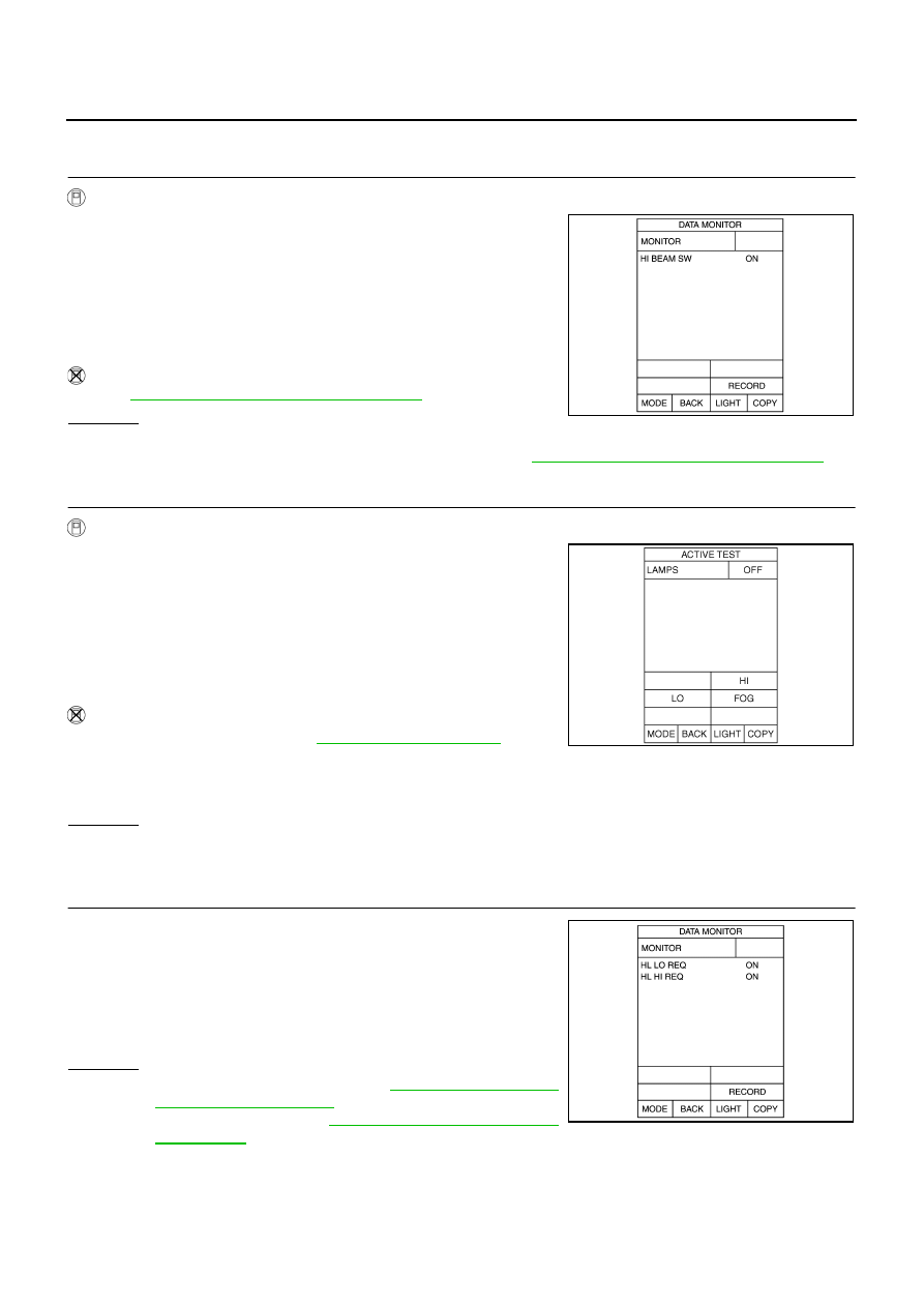
Headlamp High Beam Does Not Illuminate (Both Sides)
NKS003OW
1.
CHECK COMBINATION SWITCH INPUT SIGNAL
With CONSULT-II
1.
Select “BCM” on CONSULT-II. Select “HEAD LAMP” on
“SELECT TEST ITEM” screen.
2.
Select “DATA MONITOR” on “SELECT DIAG MODE” screen.
Make sure that “HI BEAM SW” turns ON-OFF linked with opera-
tion of lighting switch.
Without CONSULT-II
Refer to
LT-239, "Combination Switch Inspection"
OK or NG
OK
>> GO TO 2.
NG
>> Check combination switch (lighting switch). Refer to
LT-239, "Combination Switch Inspection"
2.
HEADLAMP ACTIVE TEST
With CONSULT-II
1.
Select “IPDM E/R” on CONSULT-II. Select “ACTIVE TEST” on
“SELECT DIAG MODE” screen.
2.
Select “LAMPS” on “SELECT TEST ITEM” screen.
3.
Touch “HI” screen.
4.
Make sure headlamp high beam operation.
Without CONSULT-II
1.
Start auto active test. Refer to
2.
Make sure headlamp high beam operation.
OK or NG
OK
>> GO TO 3.
NG
>> GO TO 4.
3.
CHECK IPDM E/R
1.
Select “IPDM E/R” on CONSULT-II. Select “DATA MONITOR”
on “SELECT DIAG MODE” screen.
2.
Make sure “HL LO REQ” and “HL HI REQ” turns ON when light-
ing switch is in HI position.
OK or NG
OK
NG
>> Replace BCM. Refer to
BCS-15, "Removal and Installa-
When lighting switch is
HIGH position
: HI BEAM SW ON
PKIA7585E
Headlamp high beam should operate
(Headlamp high beam repeats ON–OFF every 1 second).
Headlamp high beam should operate.
SKIA5774E
When lighting switch is
HIGH position
: HL LO REQ ON
: HL HI REQ ON
PKIA7638E
Нет комментариевНе стесняйтесь поделиться с нами вашим ценным мнением.
Текст