Infiniti M35/M45 Y50. Manual — part 879
HEADLAMP (FOR USA) - XENON TYPE -
LT-61
C
D
E
F
G
H
I
J
L
M
A
B
LT
4.
CHECK HEADLAMP INPUT SIGNAL
With CONSULT-II
1.
Turn ignition switch OFF.
2.
Disconnect front combination lamp RH and LH connector.
3.
Select “IPDM E/R” on CONSULT-II, select “ACTIVE TEST” on “SELECT DIAG MODE” screen.
4.
Select “LAMPS” on “SELECT TEST ITEM” screen.
5.
Touch “HI” screen.
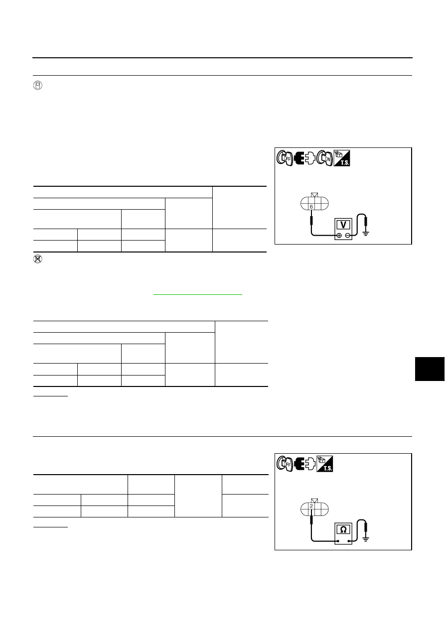
6.
When headlamp high beam is operating, check voltage between
front combination lamp (RH and LH) harness connector and
ground. (Headlamp high beam repeats ON-OFF every 1 sec-
ond.)
Without CONSULT-II
1.
Turn ignition switch OFF.
2.
Disconnect front combination lamp connector.
3.
Start auto active test. Refer to
.
4.
When headlamp high beam is operating, check voltage between front combination lamp (RH and LH) har-
ness connector and ground.
OK or NG
OK
>> GO TO 5.
NG
>> GO TO 7.
5.
CHECK HEADLAMP GROUND
1.
Turn ignition switch OFF.
2.
Check continuity between front combination lamp (RH and LH)
harness connector and ground.
OK or NG
OK
>> GO TO 6.
NG
>> Repair harness or connector.
Terminal
Voltage
(Approx.)
(+)
(-)
Front combination lamp
connector
Terminal
RH
E47
6
Ground
Battery voltage
LH
E54
6
Terminal
Voltage
(Approx.)
(+)
(-)
Front combination lamp
connector
Terminal
RH
E47
6
Ground
Battery voltage
LH
E54
6
SKIB4749E
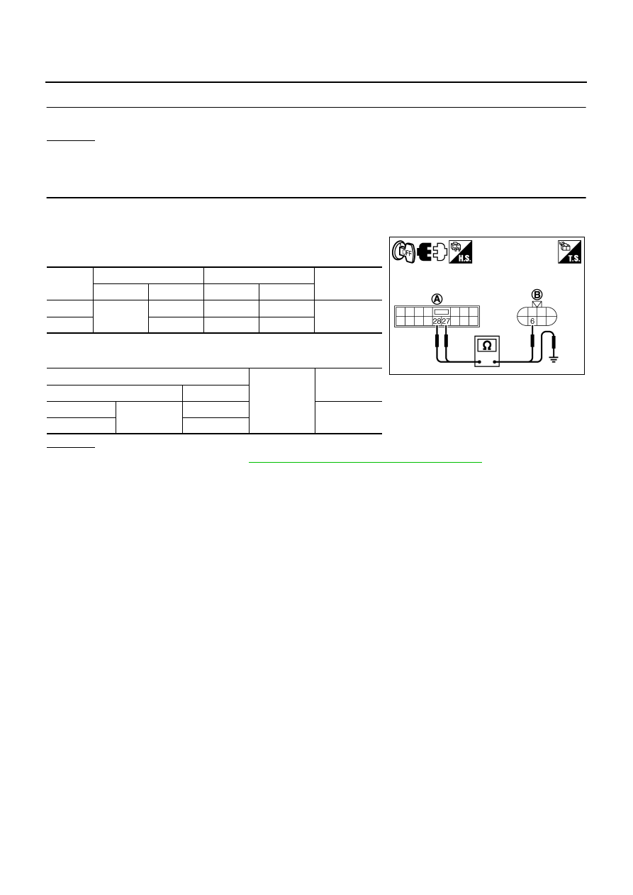
Front combination lamp
connector
Terminal
Ground
Continuity
RH
E47
2
Yes
LH
E54
2
SKIB4750E
LT-62
HEADLAMP (FOR USA) - XENON TYPE -
6.
CHECK BULB
Check bulbs of lamp (both side).
OK or NG
OK
>> Check connecting condition headlamp harness connector.
NG
>> Replace headlamp bulb.
7.
CHECK CIRCUIT BETWEEN IPDM E/R AND FRONT COMBINATION LAMP
1.
Turn ignition switch OFF.
2.
Disconnect IPDM E/R connector.
3.
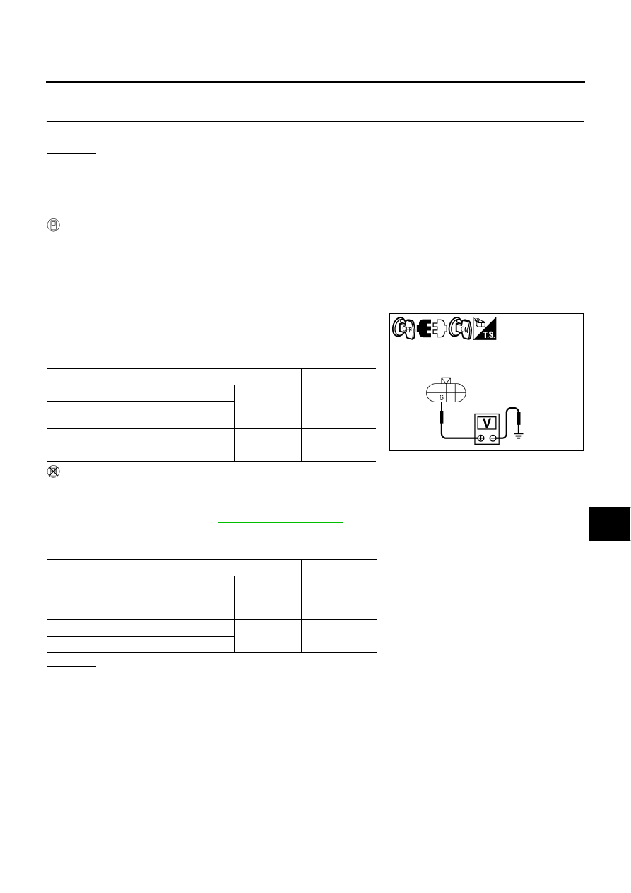
Check continuity between IPDM E/R harness connector (A) and
front combination lamp (RH and LH) harness connector (B).
4.
Check continuity between IPDM E/R harness connector (A) and
ground.
OK or NG
OK
PG-31, "Removal and Installation of IPDM E/R"
NG
>> Repair harness or connector.
Circuit
A
B
Continuity
Connector
Terminal
Connector
Terminal
RH
E7
27
E47
6
Yes
LH
28
E54
6
A
Ground
Continuity
Connector
Terminal
RH
E7
27
No
LH
28
SKIB4753E
HEADLAMP (FOR USA) - XENON TYPE -
LT-63
C
D
E
F
G
H
I
J
L
M
A
B
LT
Headlamp High Beam Does Not Illuminate (One Side)
NKS003OX
1.
CHECK BULB
Check bulb of lamp which does not illuminate.
OK or NG
OK
>> GO TO 2.
NG
>> Replace headlamp bulb.
2.
CHECK HEADLAMP INPUT SIGNAL
With CONSULT-II
1.
Turn ignition switch OFF.
2.
Disconnect front combination lamp RH or LH connector.
3.
Select “IPDM E/R” on CONSULT-II. Select “ACTIVE TEST” on “SELECT DIAG MODE” screen.
4.
Select “LAMPS” on “SELECT TEST ITEM” screen.
5.
Touch “HI” screen.
6.
When headlamp high beam is operating, check voltage between
front combination lamp RH or LH harness connector and
ground. (Headlamp high beam repeats ON-OFF every 1 sec-
ond.)
Without CONSULT-II
1.
Turn ignition switch OFF.
2.
Disconnect front combination lamp RH or LH connector.
3.
Start auto active test. Refer to
.
4.
When headlamp high beam is operating, check voltage between front combination lamp RH or LH har-
ness connector and ground.
OK or NG
OK
>> GO TO 3.
NG
>> GO TO 4.
Terminal
Voltage
(Approx.)
(+)
(-)
Front combination lamp
connector
Terminal
RH
E47
6
Ground
Battery voltage
LH
E54
6
Terminal
Voltage
(Approx.)
(+)
(-)
Front combination lamp
connector
Terminal
RH
E47
6
Ground
Battery voltage
LH
E54
6
SKIB4749E
LT-64
HEADLAMP (FOR USA) - XENON TYPE -
3.
CHECK HEADLAMP GROUND
1.
Turn ignition switch OFF.
2.
Check continuity between front combination lamp RH or LH har-
ness connector and ground.
OK or NG
OK
>> Check connecting condition headlamp harness connec-
tor.
NG
>> Repair harness or connector.
4.
CHECK CIRCUIT BETWEEN IPDM E/R AND FRONT COMBINATION LAMP
1.
Turn ignition switch OFF.
2.
Disconnect IPDM E/R connector and front combination lamp RH or LH connector.
3.
Check continuity between IPDM E/R harness connector (A) and
front combination lamp RH or LH harness connector (B).
4.
Check continuity between IPDM E/R harness connector (A) and
ground.
OK or NG
OK
PG-31, "Removal and Installation of IPDM E/R"
NG
>> Repair harness or connector.
High Beam Indicator Lamp Does Not Illuminate
NKS003OY
1.
CHECK UNIFIED METER AND A/C AMP.
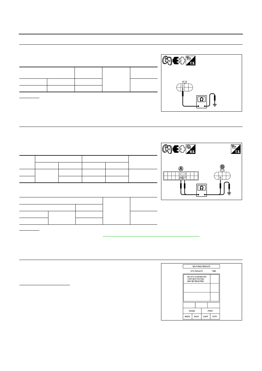
1.
Select “METER A/C AMP” on CONSULT-II, and perform self-
diagnosis for “METER A/C AMP”.
2.
Check if malfunction is indicated.
Is malfunction indicated?
YES
>> Repair or replace malfunctioning parts.
NO
>> GO TO 2.
Front combination lamp
connector
Terminal
Ground
Continuity
RH
E47
2
Yes
LH
E54
2
SKIB4750E
Circuit
A
B
Continuity
Connector
Terminal
Connector
Terminal
RH
E7
27
E47
6
Yes
LH
28
E54
6
A
Ground
Continuity
Connector
Terminal
RH
E7
27
No
LH
28
SKIB4753E
PKIA6866E
Нет комментариевНе стесняйтесь поделиться с нами вашим ценным мнением.
Текст