Infiniti M35/M45 Y50. Manual — part 877
HEADLAMP (FOR USA) - XENON TYPE -
LT-53
C
D
E
F
G
H
I
J
L
M
A
B
LT
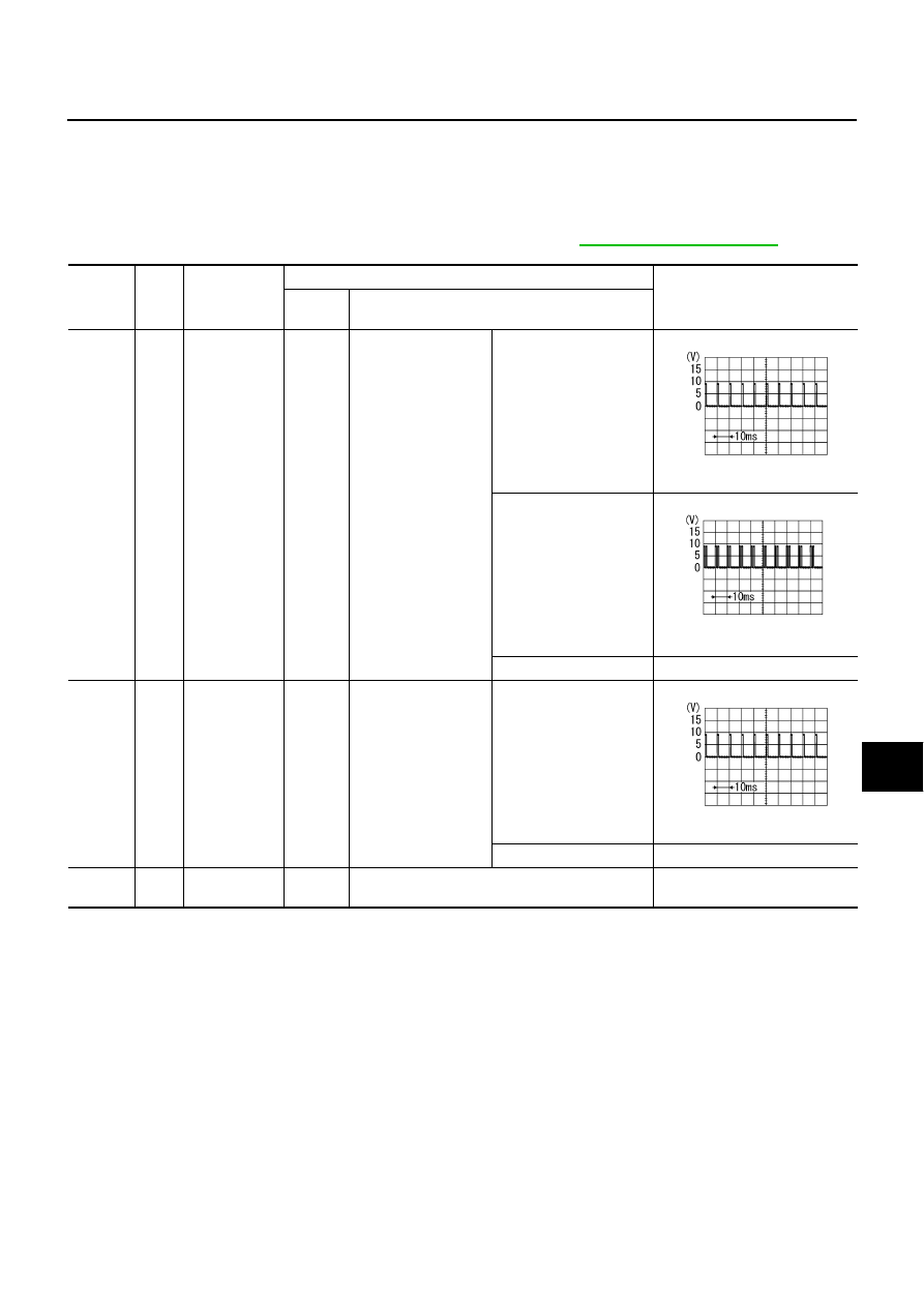
Terminals and Reference Values for BCM
NKS003OQ
CAUTION:
●
Check combination switch system terminal waveform under the loaded condition with lighting
switch, turn signal switch and wiper switch OFF not to be fluctuated by overloaded.
●
Turn wiper dial position to 4 except when checking waveform or voltage of wiper dial position.
Wiper dial position can be confirmed on CONSULT-II. Refer to
Terminal
No.
Wire
color
Signal name
Measuring condition
Reference value
Ignition
switch
Operation or condition
2
L/R
Combination
switch input 5
ON
Lighting, turn, wiper
switch
(Wiper dial position 4)
Lighting switch HI beam
(Operates only HI beam
switch)
Approx. 1.0 V
Lighting switch 2ND
Approx. 2.0 V
OFF
Approx. 0 V
3
O/L
Combination
switch input 4
ON
Lighting, turn, wiper
switch
(Wiper dial position 4)
Any of several con-
ditions below
●
Lighting switch 2ND
●
Lighting switch
PASSING (Operates
only PASSING switch)
Approx. 1.0 V
OFF
Approx. 0 V
11
V
Ignition switch
(ACC)
ACC
—
Battery voltage
PKIB4957J
PKIB4953J
PKIB4957J

LT-54
HEADLAMP (FOR USA) - XENON TYPE -
34
L
Combination
switch output 3
ON
Lighting, turn, wiper
switch
(Wiper dial position 4)
Any of several con-
ditions below
●
Lighting switch 2ND
●
Lighting switch HI
beam (Operates only
HI beam switch)
Approx. 1.2 V
OFF
Approx. 7.0 - 7.5 V
35
SB
Combination
switch output 2
ON
Lighting, turn, wiper
switch
(Wiper dial position 4)
Any of several con-
ditions below
●
Lighting switch 2ND
●
Lighting switch
PASSING (Operates
only PASSING switch)
Approx. 1.2 V
OFF
Approx. 7.0 - 7.5 V
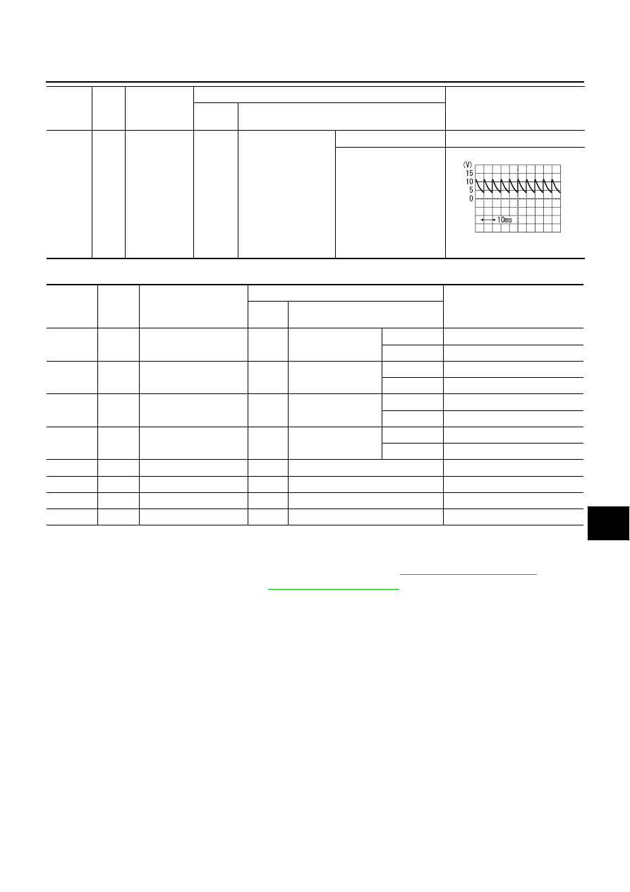
38
W
Ignition switch
(ON)
ON
—
Battery voltage
37
LG
Key switch sig-
nal
OFF
Intelligent Key is inserted into key slot.
Battery voltage
Intelligent Key is removed from key slot.
Approx. 0 V
39
L
CAN
−
H
—
—
—
40
P
CAN
−
L
—
—
—
42
P
Battery power
supply
OFF
—
Battery voltage
52
B
Ground
ON
—
Approx. 0 V
55
W
Battery power
supply
OFF
—
Battery voltage
Terminal
No.
Wire
color
Signal name
Measuring condition
Reference value
Ignition
switch
Operation or condition
PKIB4958J
PKIB4960J
PKIB4958J
PKIB4960J
HEADLAMP (FOR USA) - XENON TYPE -
LT-55
C
D
E
F
G
H
I
J
L
M
A
B
LT
Terminals and Reference Values for IPDM E/R
NKS003OR
How to Perform Trouble Diagnoses
NKS003OS
1.
Confirm the symptom or customer complaint.
2.
Understand operation description and function description. Refer to
3.
Perform the Preliminary Check. Refer to
.
4.
Check symptom and repair or replace the cause of malfunction.
5.
Does the headlamp operate normally? If YES, GO TO 6. If NO, GO TO 4.
6.
INSPECTION END
62
V
Front door
switch driver
side signal
OFF
Front door switch
driver side
ON (open)
Approx. 0 V
OFF (closed)
Approx. 7.5 - 8.0 V
Terminal
No.
Wire
color
Signal name
Measuring condition
Reference value
Ignition
switch
Operation or condition
PKIB4960J
Terminal
No.
Wire
color
Signal name
Measuring condition
Reference value
Ignition
switch
Operation or condition
20
R
Headlamp low (RH)
ON
Lighting switch 2ND
position
OFF
Approx. 0 V
ON
Battery voltage
27
BR
Headlamp high (RH)
ON
Lighting switch HIGH
or PASSING position
OFF
Approx. 0 V
ON
Battery voltage
28
R/Y
Headlamp high (LH)
ON
Lighting switch HIGH
or PASSING position
OFF
Approx. 0 V
ON
Battery voltage
30
R/B
Headlamp low (LH)
ON
Lighting switch 2ND
position
OFF
Approx. 0 V
ON
Battery voltage
38
B
Ground
ON
—
Approx. 0 V
49
L
CAN
−
H
—
—
—
50
P
CAN
−
L
—
—
—
51
B
Ground
ON
—
Approx. 0 V
LT-56
HEADLAMP (FOR USA) - XENON TYPE -
Preliminary Check
NKS003OT
CHECK POWER SUPPLY AND GROUND CIRCUIT
1.
CHECK FUSES AND FUSIBLE LINK
Check for blown fuses and fusible link.
LT-47, "Wiring Diagram — H/LAMP —"
OK or NG
OK
>> GO TO 2.
NG
>> If fuse or fusible link is blown, be sure to eliminate cause of malfunction before installing new fuse
PG-3, "POWER SUPPLY ROUTING CIRCUIT"
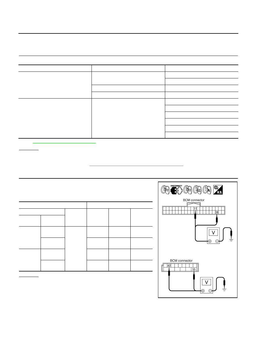
2.
CHECK POWER SUPPLY CIRCUIT
1.
Turn ignition switch OFF.
2.
Disconnect BCM connector.
3.
Check voltage between BCM harness connector and ground.
OK or NG
OK
>> GO TO 3.
NG
>> Repair harness or connector.
Unit
Power source
Fuse and fusible link No.
BCM
Battery
F
21
Ignition switch ON or START position
1
Ignition switch ACC or ON position
6
IPDM E/R
Battery
71
72
74
76
78
86
Terminal
Ignition switch position
(+)
(
−
)
OFF
ACC
ON
BCM
connector
Terminal
M1
11
Ground
Approx.
0 V
Battery
voltage
Battery
voltage
38
Approx.
0 V
Approx.
0 V
Battery
voltage
M2
42
Battery
voltage
Battery
voltage
Battery
voltage
55
Battery
voltage
Battery
voltage
Battery
voltage
PKIA5204E
Нет комментариевНе стесняйтесь поделиться с нами вашим ценным мнением.
Текст