Infiniti M35/M45 Y50. Manual — part 774
FUEL LEVEL SENSOR UNIT, FUEL FILTER AND FUEL PUMP ASSEMBLY
FL-7
C
D
E
F
G
H
I
J
K
L
M
A
FL
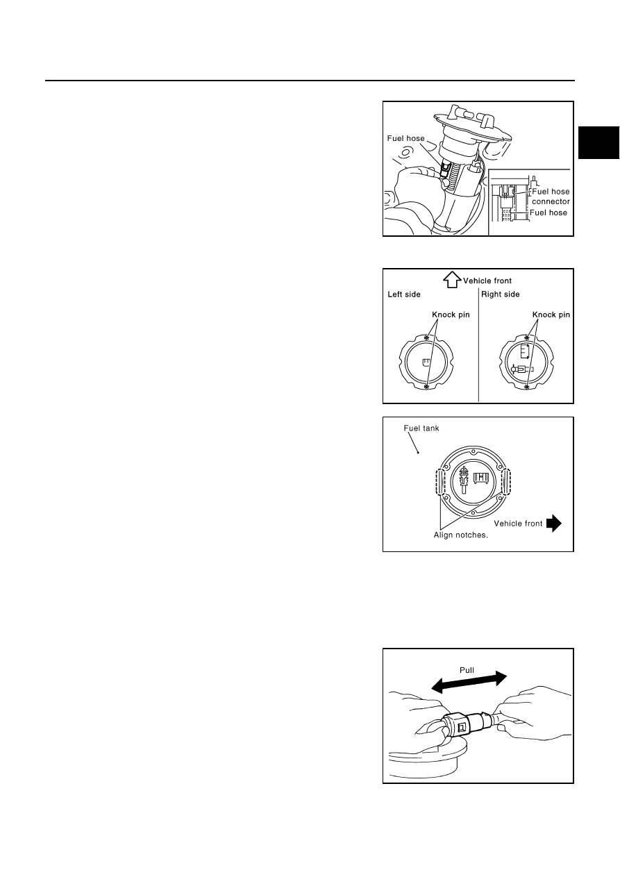
Fuel hose
●
When installing fuel hose connector insert them fully until a click
sound of full stopper engagement is heard.
Main and Sub Fuel Level Sensor Unit
●
Face main and sub fuel level sensor units as shown in the fig-
ure, and install them with the knock pin on back aligned with pin
hole on fuel tank.
●
Install retainer so that its notch becomes parallel with the notch
on fuel tank.
●
Tighten retainer mounting bolts evenly.
Quick Connector
Connect quick connector as follows:
1.
Check the connection for damage or any foreign materials.
2.
Align the connector with the tube, then insert the connector straight into the tube until a click sound is
heard.
3.
After connecting, make sure that the connection is secure by following method.
●
Pull the tube and the connector to make sure they are
securely connected.
●
Visually confirm that the two retainer tabs are connected to
the connector.
INSPECTION AFTER INSTALLATION
Use the following procedure to check for fuel leaks.
PBIC1579E
PBIC1065E
PBIC1652E
PBIC1653E
FL-8
FUEL LEVEL SENSOR UNIT, FUEL FILTER AND FUEL PUMP ASSEMBLY
1.
Turn ignition switch “ON” (with engine stopped), then check connections for leaks by applying fuel pres-
sure to fuel piping.
2.
Start engine and let it idle and make sure there are no fuel leaks at the fuel system connections.
Components
NBS005RC
Disassembly and Assembly
NBS005RD
CAUTION:
Sub fuel level sensor unit cannot be disassembled and should be replaced as a unit.
DISASSEMBLY
Remove fuel level sensor unit as follows.
1.
Disconnect harness connector.
●
Hold connector by fingers and pull it out, because there is no
stopper release tab.
2.
Using suitable tool, pull up tabs points as shown in the figure
(two points) to release the lock.
CAUTION:
Be careful not to damage it.
3.
After fixing tabs are disengaged, slide fuel level sensor unit out
in direction shown by the arrow.
CAUTION:
Do not disassemble fuel filter and fuel pump assembly.
1.
Fuel level sensor unit
2.
Fuel filter and fuel pump assembly
PBIC1081E
PBIC1078E
PBIC1654E
PBIC1080E
FUEL LEVEL SENSOR UNIT, FUEL FILTER AND FUEL PUMP ASSEMBLY
FL-9
C
D
E
F
G
H
I
J
K
L
M
A
FL
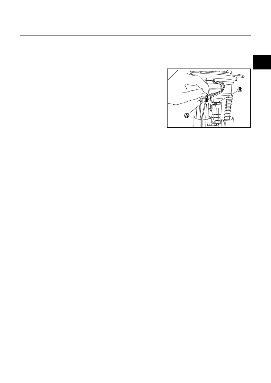
ASSEMBLY
1.
Check for damage of fuel level sensor unit installation position on the side of fuel filter and fuel pump
assembly.
2.
Slide fuel level sensor unit until it aligns to installation groove, then insert it until it stops.
●
After inserting, apply force in reverse direction (removal direction) to ensure it cannot be pulled out.
3.
Connect the black (A) and white (B) harnesses so that they are
in the positions shown in the figure.
●
Securely insert harness connector until it stops.
PBIC3387E
FL-10
FUEL TANK
FUEL TANK
PFP:17202
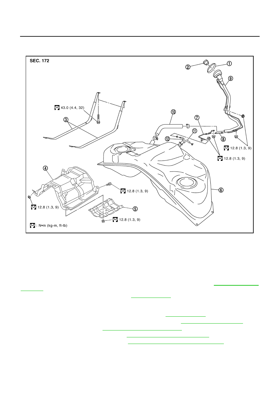
Components
NBS005RE
Removal and Installation
NBS005RF
REMOVAL
WARNING:
Be sure to read “General Precautions” when working on the fuel system. Refer to
●
Drain fuel from fuel tank if necessary. Refer to
●
Perform work on level place.
1.
Perform steps 2 to 7 of “REMOVAL” in “ FUEL LEVEL SENSOR UNIT, FUEL FILTER AND FUEL PUMP
ASSEMBLY” on main and sub fuel level sensor units. Refer to
2.
Remove exhaust front tube, center muffler and main muffler. Refer to
3.
Remove propeller shaft. Refer to
4.
Remove parking rear brake cables. Refer to
5.
Remove rear suspension assembly. Refer to
RSU-5, "REAR SUSPENSION ASSEMBLY"
.
6.
Remove fuel tank protector.
1.
Grommet
2.
Fuel filler cap
3.
Fuel tank mounting band
4.
Fuel tank protector
5.
Insulator
6.
Fuel tank
7.
Vent tube
8.
Vent hose
9.
Fuel filler tube
10. Fuel filler hose
11.
EVAP hose
12. Vent hose
PBIC3201E
Нет комментариевНе стесняйтесь поделиться с нами вашим ценным мнением.
Текст