Infiniti M35/M45 Y50. Manual — part 773
FUEL SYSTEM
FL-3
C
D
E
F
G
H
I
J
K
L
M
A
FL
FUEL SYSTEM
PFP:17503
Checking Fuel Lines
NBS005R8
Inspect fuel lines, fuel filler cap and fuel tank for improper attach-
ment, leaks, cracks, damage, loose connections, chafing or deterio-
ration.
If necessary, repair or replace damaged parts.
General Precautions
NBS005R9
WARNING:
When replacing fuel line parts, be sure to observe the following.
●
Put a “CAUTION: FLAMMABLE” sign in the workshop.
●
Be sure to work in a well ventilated area and furnish workshop with a CO
2
fire
extinguisher.
●
Do not smoke while servicing fuel system. Keep open flames and sparks away from the work area.
CAUTION:
●
Use gasoline required by the regulations for octane number. Refer to
(Unleaded Premium Gasoline Required) (VK45DE Engine Models)"
.
●
Before removing fuel line parts, perform out the following procedures:
–
Put drained fuel in an explosion-proof container and put the lid on securely. Keep the container in
safe area.
–
Release fuel pressure from the fuel lines. Refer to
EC-88, "FUEL PRESSURE RELEASE"
EC-790, "FUEL PRESSURE RELEASE"
–
Disconnect the battery cable from the negative terminal.
●
Always replace O-ring and clamps with new ones.
●
Do not kink or twist tubes when they are being installed.
●
Do not tighten hose clamps excessively to avoid damaging hoses.
●
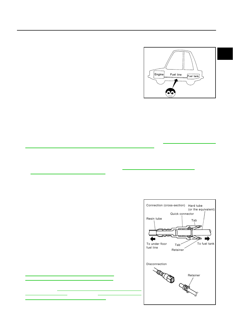
After connecting fuel tube quick connectors, make sure
quick connectors are secure.
Ensure that connector and resin tube do not contact any
adjacent parts.
●
After installing tubes, make sure there is no fuel leakage at
connections in the following steps.
–
Apply fuel pressure to fuel lines with turning ignition switch
“ON” (with engine stopped). Then check for fuel leaks at
connections.
–
Start engine and rev it up and check for fuel leaks at con-
nections.
●
Use only a genuine NISSAN fuel filler cap as a replacement.
If an incorrect fuel filler cap is used, the “MIL” may come
on.
●
For servicing “Evaporative Emission System” parts, refer to
EC-39, "EVAPORATIVE EMISSION SYSTEM"
(VQ35DE) or
EC-741, "EVAPORATIVE EMISSION SYSTEM"
(VK45DE).
●
For servicing“On Board Refueling Vapor Recovery (ORVR)”
parts, refer to
EC-46, "ON BOARD REFUELING VAPOR
REFUELING VAPOR RECOVERY (ORVR)"
(VK45DE).
SMA803A
SBIA0504E
FL-4
FUEL LEVEL SENSOR UNIT, FUEL FILTER AND FUEL PUMP ASSEMBLY
FUEL LEVEL SENSOR UNIT, FUEL FILTER AND FUEL PUMP ASSEMBLY
PFP:17042
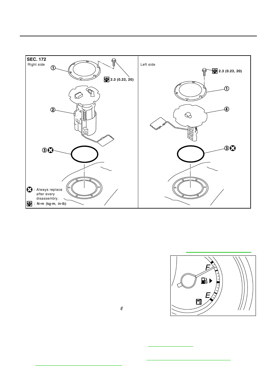
Components
NBS005RA
Removal and Installation
NBS005RB
REMOVAL
WARNING:
Read “General Precautions” when working on the fuel system. Refer to
1.
Check fuel level on fuel gauge. If fuel gauge indicates more than
the level as shown in the figure (full or almost full), drain fuel
from fuel tank until fuel gauge indicates level as shown in the fig-
ure or below.
NOTE:
Because fuel will be spilled when removing main and sub fuel
level sensor units for the top of the fuel is above the main and
sub fuel level sensor units installation surface.
●
As a guide, fuel level becomes the position as shown in the
figure or below when approximately 20 (5-1/4 US gal, 4-3/8
Imp gal) of fuel are drained from fuel tank.
●
In a case that fuel pump does not operate, perform the follow-
ing procedure.
a.
Insert hose of less than 25 mm (0.98 in) in diameter into fuel filler tube through fuel filler opening to draw
fuel from fuel filler tube.
b.
Disconnect fuel filler hose from fuel filler tube. Refer to
c.
Insert fuel tube into fuel tank through fuel filler hose to draw fuel from fuel tank.
2.
Release the fuel pressure from the fuel lines. Refer to
EC-88, "FUEL PRESSURE RELEASE"
or
EC-790, "FUEL PRESSURE RELEASE"
1.
Retainer
2.
Main fuel level sensor unit, fuel filter
and fuel pump assembly
3.
O-ring
4.
Sub fuel level sensor unit
PBIC1585E
PBIC4760E
FUEL LEVEL SENSOR UNIT, FUEL FILTER AND FUEL PUMP ASSEMBLY
FL-5
C
D
E
F
G
H
I
J
K
L
M
A
FL
3.
Open fuel filler lid.
4.
Open filler cap and release the pressure inside fuel tank.
5.
Remove rear seat cushion. Refer to
6.
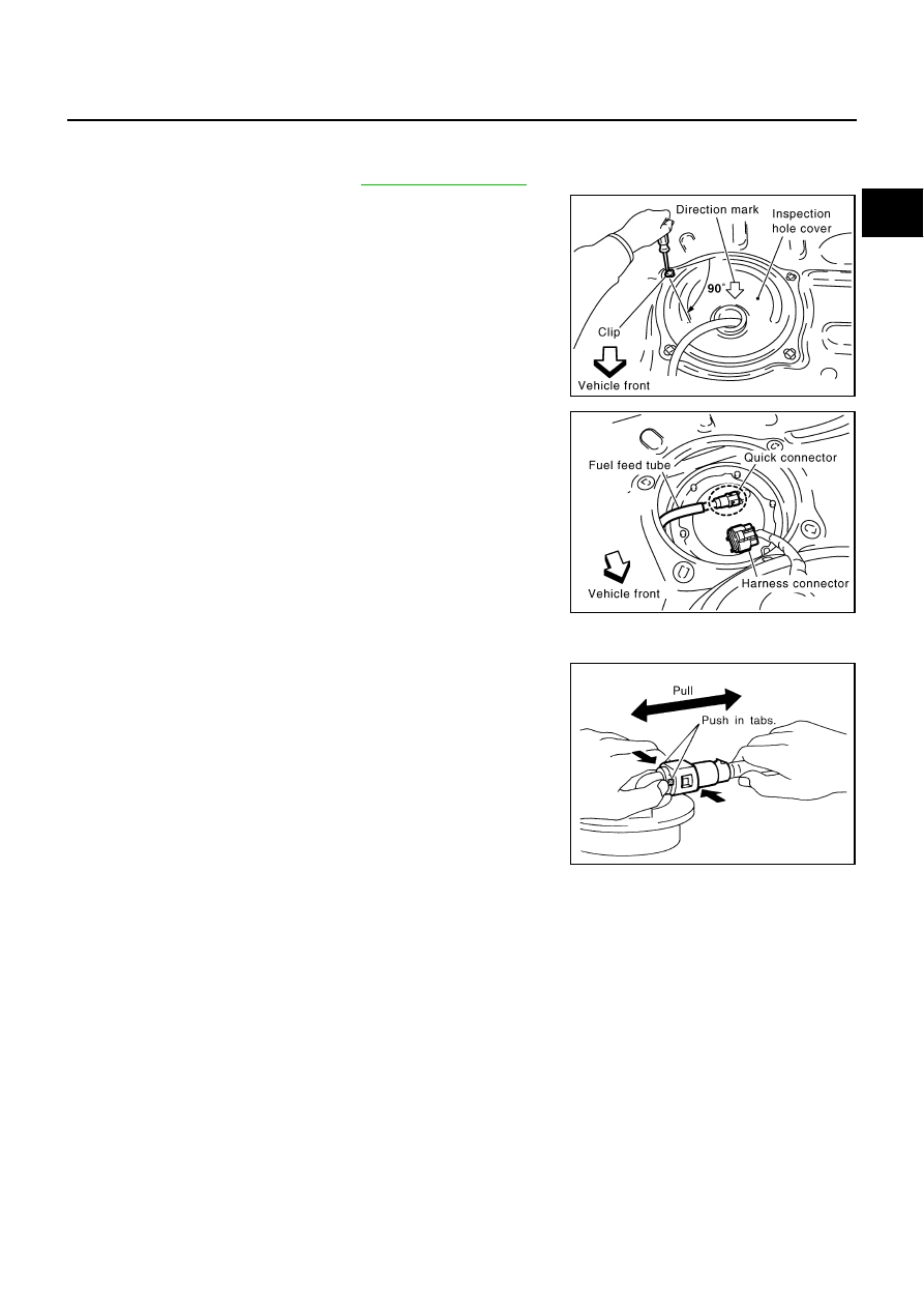
Peel off floor carpet, then remove inspection hole cover units by
turning clips clockwise by 90 degrees.
7.
Disconnect harness connector and fuel feed tube.
Disconnect quick connector as follows:
●
Hold the sides of connector, push in tabs and pull out fuel feed
tube.
●
If quick connector sticks to tube of main fuel level sensor unit,
push and pull quick connector several times until they start to
move.Then disconnect them by pulling.
Right side
: Main fuel level sensor unit, fuel filter
and fuel pump assembly
Left side
: Sub fuel level sensor unit
PBIC1576E
PBIC1577E
SFE562A
FL-6
FUEL LEVEL SENSOR UNIT, FUEL FILTER AND FUEL PUMP ASSEMBLY
CAUTION:
●
Quick connector can be disconnected when the tabs
are completely depressed. Do not twist it more than
necessary.
●
Do not use any tools to disconnected quick connector.
●
Keep resin tube away from heat. Be especially careful
when welding near the resin tube.
●
Prevent acid liquid such as battery electrolyte, etc.
from getting on resin tube.
●
Do not bend or twist resin tube during installation and
disconnection.
●
Do not remove the remaining retainer on hard tube (or
the equivalent) except when resin tube or retainer is
replaced.
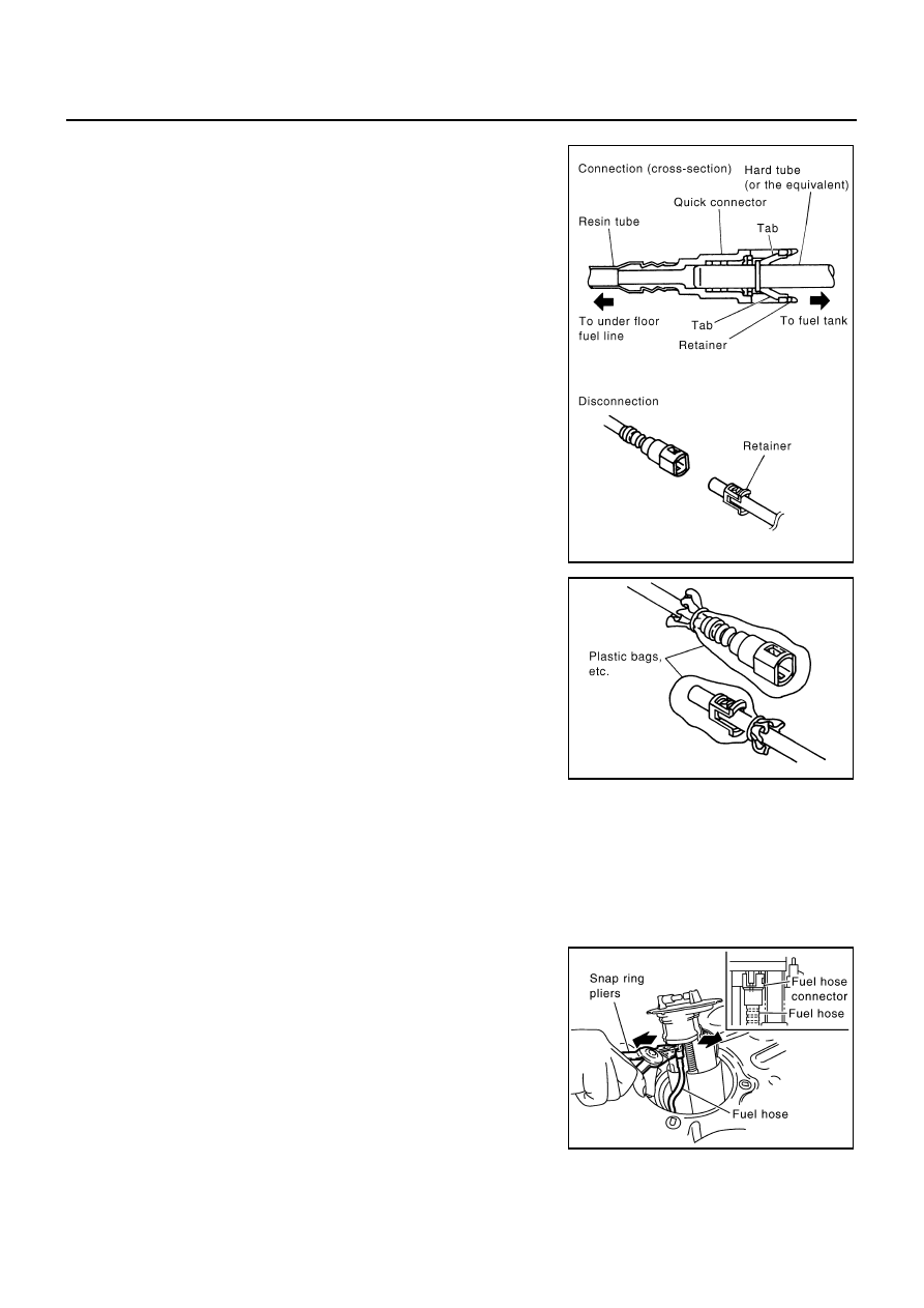
●
When resin tube or hard tube (or the equivalent) is
replaced, also replace retainer with new one.
●
To keep the connecting portion clean and to avoid
damage and foreign materials, cover them completely
with plastic bags or something similar.
8.
Remove main fuel level sensor unit, fuel filter and fuel pump assembly, and sub fuel level sensor unit as
follows:
CAUTION:
●
Do not bend float arm during removal.
●
Avoid impacts such as falling when handling components.
a.
Removal of main fuel level sensor unit, fuel filter and fuel pump assembly:
i.
Remove retainer.
ii.
Raise main fuel level sensor unit, fuel filter and fuel pump
assembly, and using snap ring pliers, remove fuel hose connec-
tor.
CAUTION:
Be careful not to damage fuel hose connector by expanding
them excessively.
b.
Removal of sub fuel level sensor unit:
i.
Remove retainer.
ii.
Raise and release sub fuel level sensor unit to remove.
INSTALLATION
Note to the following, and install in the reverse order of removal.
Retainer color: Green
SBIA0504E
PBIC0163E
PBIC1578E
Нет комментариевНе стесняйтесь поделиться с нами вашим ценным мнением.
Текст