Infiniti M35/M45 Y50. Manual — part 362
UNIFIED METER AND A/C AMP
DI-31
C
D
E
F
G
H
I
J
L
M
A
B
DI
CONSULT-II Function (METER A/C AMP)
NKS003UI
CONSULT-II can display each diagnostic item using the diagnostic test modes shown following.
CONSULT-II BASIC OPERATION
Refer to
GI-38, "CONSULT-II Start Procedure"
.
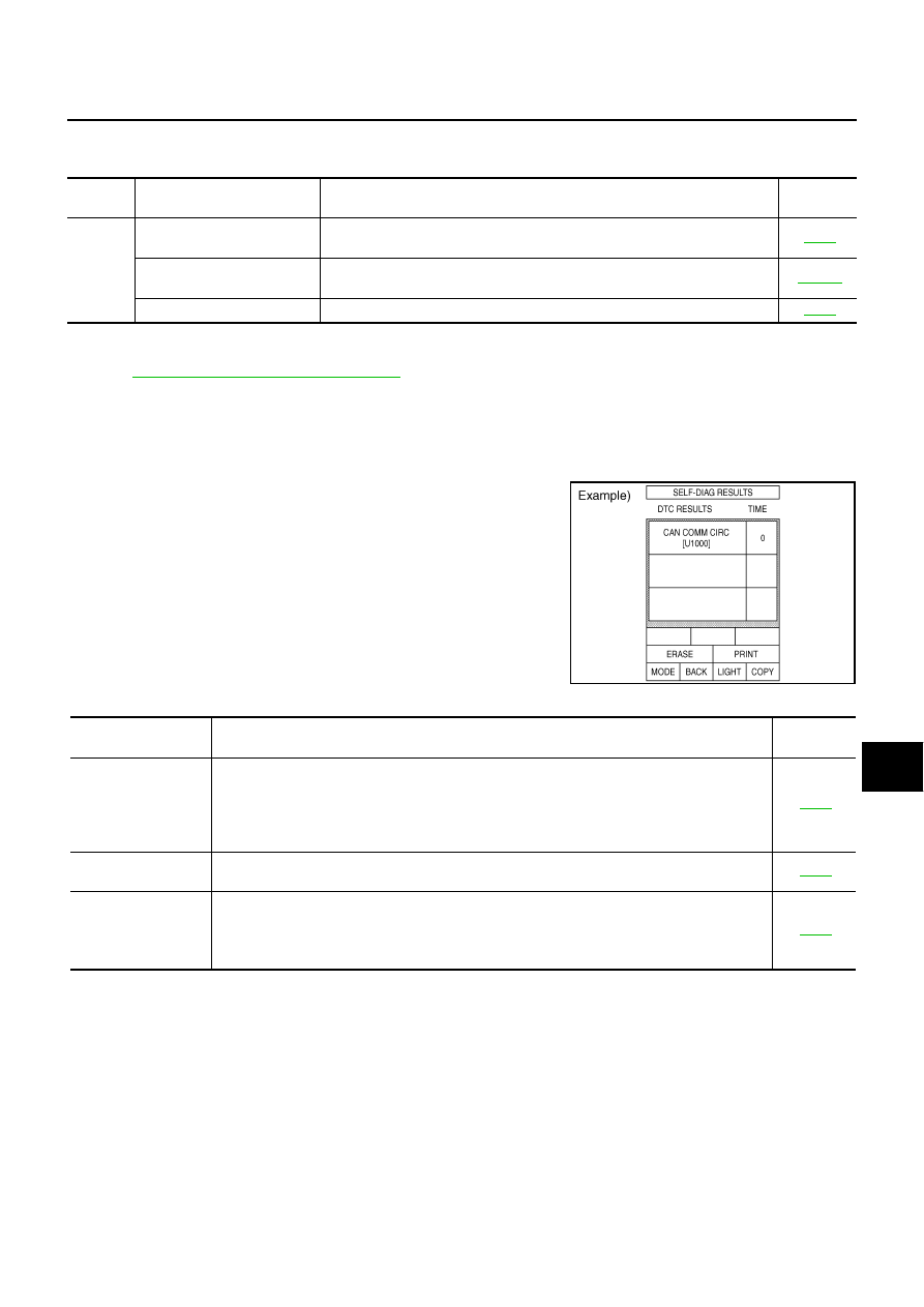
SELF-DIAG RESULTS
Operation Procedure
1.
Touch “METER A/C AMP” on “SELECT SYSTEM” screen.
2.
Touch “SELF-DIAG RESULTS” on “SELECT DIAG MODE” screen.
3.
Self-diagnosis results are displayed.
Display Item List
NOTE:
“TIME” means the following.
●
0: Means detected malfunction at present. (From malfunction detection to turning ignition switch OFF)
●
1-63: Means detected malfunction in past. (Displays number of ignition switch OFF
→
ON after detecting
malfunction. “Self-diagnosis result” is erased when exceeding “63”.)
System
Diagnosis mode
Description
Reference
page
METER
A/C AMP
SELF-DIAG RESULTS
Unified meter and A/C amp. checks the conditions and displays memorized
error.
CAN DIAG SUPPORT MNTR
The results of transmit/receive diagnosis of CAN communication can be
read.
DATA MONITOR
Displays unified meter and A/C amp. input data in real time.
SKIA4956E
Display item [Code]
Malfunction is detected when...
Reference
page
CAN COMM CIRC
[U1000]
Malfunction is detected in CAN communication.
CAUTION:
Even when there is no malfunction on CAN communication system, malfunction may be
misinterpreted when battery has low voltage (when maintaining 7 - 8 V for about 2 sec-
onds) or 10A fuse [No. 19, located in the fuse block (J/B)] is disconnected.
METER COMM CIRC
[B2202]
Malfunction is detected in communication between combination meter and unified meter and
A/C amp.
VEHICLE SPEED
CIRC
[B2205]
When an erroneous speed signal is input for 1 seconds.
CAUTION:
Even when there is no malfunction on speed signal system, malfunction may be misin-
terpreted when battery has low voltage (when maintaining 7 - 8 V for about 2 seconds).
DI-32
UNIFIED METER AND A/C AMP
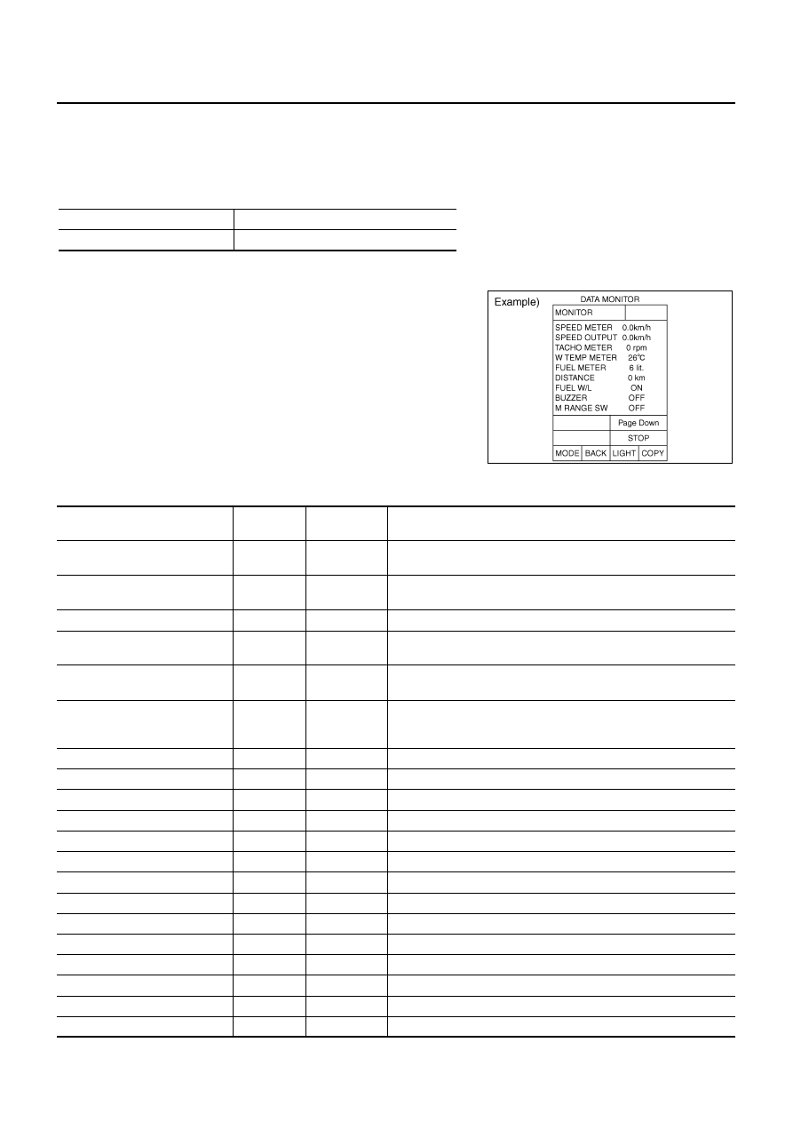
DATA MONITOR
Operation Procedure
1.
Touch “METER A/C AMP” on “SELECT SYSTEM” screen.
2.
Touch “DATA MONITOR” on “SELECT DIAG MODE” screen.
3.
Touch either “MAIN SIGNALS” or “SELECTION FROM MENU” on the “DATA MONITOR” screen.
4.
When “SELECTION FROM MENU” is selected, touch individual items to be monitored. When “MAIN SIG-
NALS” is selected, main items will be monitored.
5.
Touch “START”.
6.
Touch “RECORD” while monitoring, then the status of the moni-
tored item can be recorded. To stop recording, touch “STOP”.
Display Item List
X: Applicable
MAIN SIGNALS
Monitors main signals.
SELECTION FROM MENU
Selects and monitors individual signal.
SKIA4957E
Display item [Unit]
MAIN
SIGNALS
SELECTION
FROM MENU
Description
SPEED METER [km/h] or [mph]
X
X
Displays the value of vehicle speed signal, which is input from ABS
actuator and electric unit (control unit).
SPEED OUTPUT [km/h] or [mph]
X
X
Displays the value of vehicle speed signal, which is transmitted to
each unit with CAN communication.
TACHO METER [rpm]
X
X
Displays the value of engine speed signal, which is input from ECM.
W TEMP METER [
°
C] or [
°
F]
X
X
Displays the value of engine coolant temperature signal, which is
input from ECM.
FUEL METER [lit.]
X
X
Displays the value, which processes a resistance signal from fuel
gauge.
DISTANCE [km] or [mile]
X
X
Displays the value, which is calculated by vehicle speed signal from
ABS actuator and electric unit (control unit), fuel gauge and fuel
consumption from ECM.
FUEL W/L [ON/OFF]
X
X
Displays [ON/OFF] condition of low-fuel warning lamp.
MIL [ON/OFF]
X
Displays [ON/OFF] condition of malfunction indicator lamp.
AIR PRES W/L [ON/OFF]
X
Displays [ON/OFF] condition of low tire pressure warning lamp.
SEAT BELT W/L [ON/OFF]
X
Displays [ON/OFF] condition of seat belt warning lamp.
BUZZER [ON/OFF]
X
X
Displays [ON/OFF] condition of buzzer.
DOOR W/L [ON/OFF]
X
Displays [ON/OFF] condition of door warning lamp.
HI-BEAM IND [ON/OFF]
X
Displays [ON/OFF] condition of high beam indicator.
TURN IND [ON/OFF]
X
Displays [ON/OFF] condition of turn indicator.
FR FOG IND [ON/OFF]
X
Displays [ON/OFF] condition of front fog indicator.
OIL W/L [ON/OFF]
X
Displays [ON/OFF] condition of oil pressure warning lamp.
VDC/TCS IND [ON/OFF]
X
Displays [ON/OFF] condition of VDC/TCS OFF indicator lamp.
ABS W/L [ON/OFF]
X
Displays [ON/OFF] condition of ABS warning lamp.
SLIP IND [ON/OFF]
X
Displays [ON/OFF] condition of SLIP indicator lamp.
BRAKE W/L [ON/OFF]
X
Displays [ON/OFF] condition of brake warning lamp. *
UNIFIED METER AND A/C AMP
DI-33
C
D
E
F
G
H
I
J
L
M
A
B
DI
NOTE:
Monitored item that does not match the vehicle is deleted from the display automatically.
*: Monitor keeps indicating “OFF” when brake warning lamp is on by the parking brake operation or low brake fluid level.
KEY Y/G W/L [ON/OFF]
X
Displays [ON/OFF] condition of key warning lamp.
PNP P SW [ON/OFF]
X
X
Displays [ON/OFF] condition of inhibitor switch P range.
M RANGE SW [ON/OFF]
X
X
Displays [ON/OFF] condition of manual mode range switch.
NM RANGE SW [ON/OFF]
X
X
Displays [ON/OFF] condition of except for manual mode range
switch.
AT SFT UP SW [ON/OFF]
X
X
Displays [ON/OFF] condition of A/T shift-up switch.
AT SFT DWN SW [ON/OFF]
X
X
Displays [ON/OFF] condition of A/T shift-down switch.
AT P MODE SW
X
Displays [ON/OFF] condition of A/T POWER mode switch.
AT S MODE SW
X
Displays [ON/OFF] condition of A/T SNOW mode switch.
BRAKE SW [ON/OFF] *
X
Displays [ON/OFF] condition of brake switch (stop lamp switch).
AT-M IND [ON/OFF]
X
X
Displays [ON/OFF] condition of A/T manual mode indicator.
AT-M GEAR [5-1]
X
X
Displays [5-1] condition of A/T manual mode gear position.
P RANGE IND [ON/OFF]
X
X
Displays [ON/OFF] condition of A/T shift P range indicator.
R RANGE IND [ON/OFF]
X
X
Displays [ON/OFF] condition of A/T shift R range indicator.
N RANGE IND [ON/OFF]
X
X
Displays [ON/OFF] condition of A/T shift N range indicator.
D RANGE IND [ON/OFF]
X
X
Displays [ON/OFF] condition of A/T shift D range indicator.
AT CHECK W/L [ON/OFF]
X
Displays [ON/OFF] condition of A/T indicator.
CRUISE IND [ON/OFF]
X
Displays [ON/OFF] condition of CRUISE indicator.
SET IND [ON/OFF]
X
Displays [ON/OFF] condition of SET indicator.
CRUISE W/L [ON/OFF]
X
Displays [ON/OFF] condition of CRUISE warning lamp.
4WD W/L [ON/OFF]
X
Displays [ON/OFF] condition of AWD warning lamp.
AFS OFF IND [ON/OFF]
X
Displays [ON/OFF] condition of AFS OFF indicator.
Display item [Unit]
MAIN
SIGNALS
SELECTION
FROM MENU
Description
DI-34
UNIFIED METER AND A/C AMP
Power Supply and Ground Circuit Inspection
NKS003UJ
1.
CHECK FUSE
Check for blown fuses.
OK or NG
OK
>> GO TO 2.
NG
>> Be sure to eliminate cause of malfunction before installing new fuse. Refer to
2.
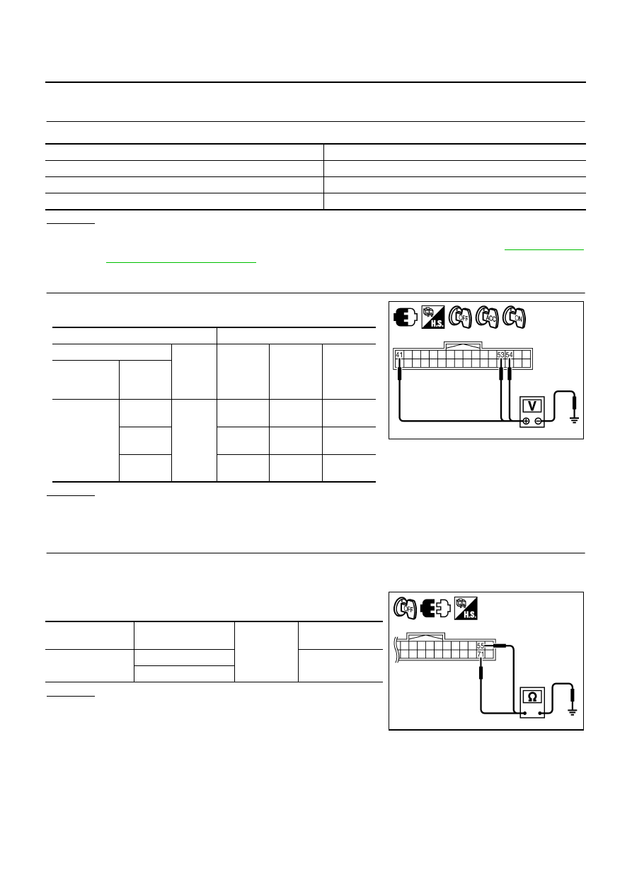
CHECK POWER SUPPLY CIRCUIT
Check voltage between unified meter and A/C amp. harness con-
nector terminals and ground.
OK or NG
OK
>> GO TO 3.
NG
>> Check harness between unified meter and A/C amp. and fuse.
3.
CHECK GROUND CIRCUIT
1.
Turn ignition switch OFF.
2.
Disconnect unified meter and A/C amp. connector.
3.
Check continuity between unified meter and A/C amp. harness
connector and ground.
OK or NG
OK
>> INSPECTION END
NG
>> Repair harness or connector.
Power source
Fuse No.
Battery
19
Ignition switch ACC or ON
6
Ignition switch ON or START
12
Terminals
Ignition switch position
(+)
(–)
OFF
ACC
ON
Unified meter
and A/C amp.
connector
Terminal
M65
54
Ground
Battery
voltage
Battery
voltage
Battery
voltage
41
0 V
Battery
voltage
Battery
voltage
53
0 V
0 V
Battery
voltage
PKIB7645E
Unified meter and
A/C amp. connector
Terminal
Ground
Continuity
M65
55
Yes
71
PKIB7646E
Нет комментариевНе стесняйтесь поделиться с нами вашим ценным мнением.
Текст