Infiniti M35/M45 Y50. Manual — part 361
COMBINATION METERS
DI-27
C
D
E
F
G
H
I
J
L
M
A
B
DI
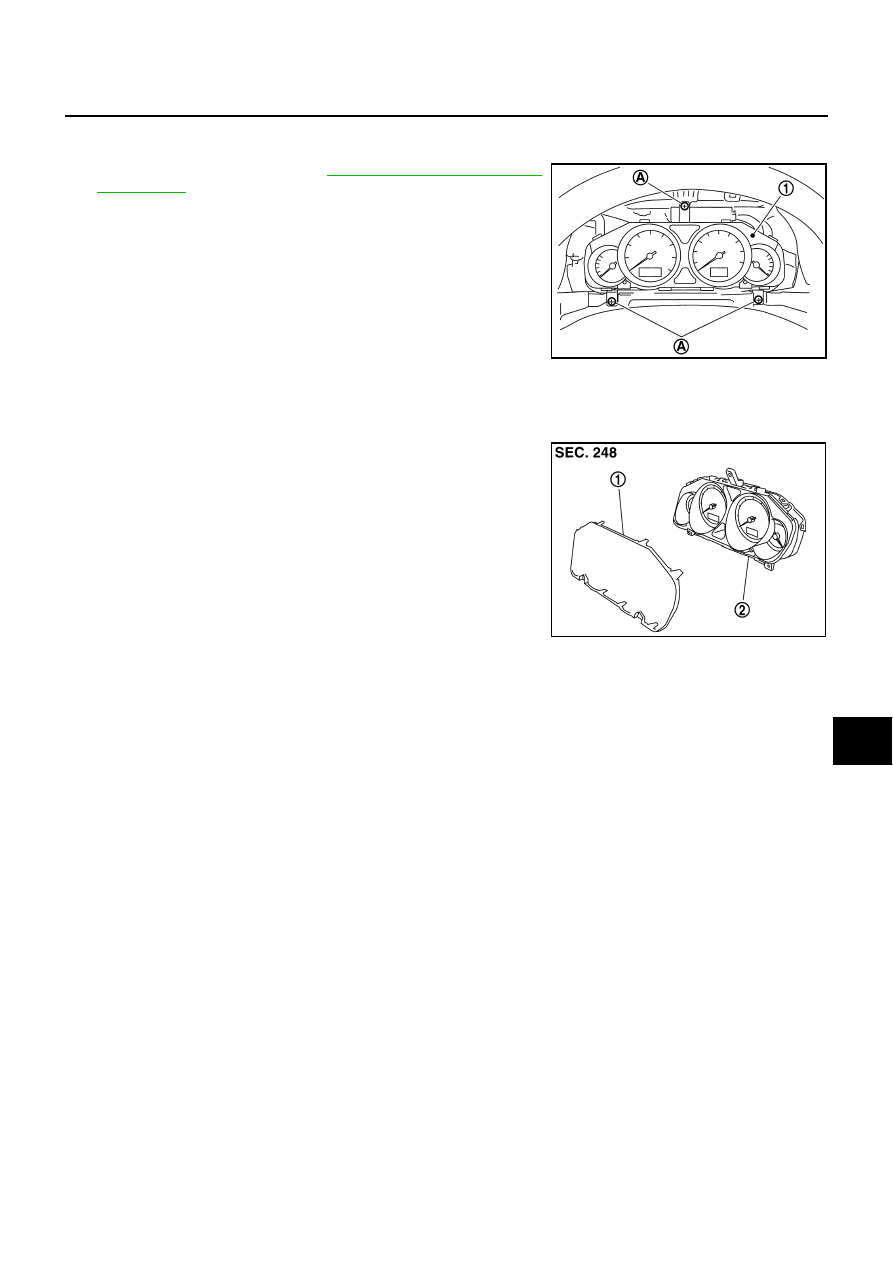
Removal and Installation of Combination Meter
NKS003UE
REMOVAL
1.
Remove cluster lid A. Refer to
.
2.
Remove the screws (A) using power tools, and pull out combina-
tion meter (1).
3.
Disconnect connector, and remove combination meter (1).
INSTALLATION
Installation is the reverse order of removal.
Disassembly and Assembly of Combination Meter
NKS003UF
DISASSEMBLY
Disengage tabs to separate front cover.
ASSEMBLY
Assembly is the reverse order of disassembly.
SKIB4957E
SKIB2952J
1.
Front cover
2.
Unified meter control unit
DI-28
UNIFIED METER AND A/C AMP
UNIFIED METER AND A/C AMP
PFP:27760
System Description
NKS003UG
For the unified meter and A/C amp., the signal required for controlling the combination meter are integrated in
the A/C auto amp.
COMBINATION METER CONTROL FUNCTION
●
Unified meter and A/C amp. inputs necessary information for combination meter from each unit with CAN
communication and so on.
●
Unified meter and A/C amp. outputs signals with communication line (TX, RX) between unified meter and
A/C amp. and combination meter.
●
Unified meter and A/C amp. corresponds a CONSULT-II function (self-diagnostic results, CAN diagnostic
support monitor and data monitor).
Input/output Signals
Between unified meter and A/C amp. and combination meter.
Unit
Input from combination meter
Output to combination meter
Unified meter and A/C amp.
●
Refuel status signal
●
Low-fuel warning lamp condition signal
●
Delivery destination data signal
●
Combination meter receive error signal
●
Combination meter specifications signal
●
Odo date signal
●
Vehicle speed signal
●
Turn indicator signal
●
High beam request signal
●
Ring illumination request signal
●
Position light request signal
●
Front fog lamp request signal
●
SET indicator lamp signal
●
CRUISE indicator lamp signal
●
Engine speed signal
●
Fuel level sensor signal (resistance value)
●
Engine coolant temperature signal
●
CAN communication condition signal of A/T
●
A/T position indicator signal
●
Manual mode indicator signal
●
A/T CHECK warning lamp signal
●
AWD warning lamp signal
●
Low tire pressure warning lamp signal
●
VDC OFF indicator lamp signal
●
SLIP indicator lamp signal
●
ABS warning lamp signal
●
Brake warning lamp signal
●
Malfunction indicator lamp signal
●
Oil pressure switch signal
●
Door switch signal
●
Buzzer request signal
●
ICC warning lamp signal
●
Meter display signal
●
AFS OFF indicator signal
UNIFIED METER AND A/C AMP
DI-29
C
D
E
F
G
H
I
J
L
M
A
B
DI
A/C AUTO AMP. FUNCTION
Unified meter and A/C amp. controls each operation for A/C auto amp. Regarding A/C control, refer to
in ATC section.
OTHER FUNCTIONS
Drive Computer Function
The signals required for the distance to empty (DTE) display are centralized in the unified meter and A/C
amp., converted into data, and transmit to the AV control unit (without NAVI) or NAVI control unit (with NAVI)
with CAN communication.
Signal Buffer Function
Unified meter and A/C amp. transmits each signal to other units with CAN communication.
DI-30
UNIFIED METER AND A/C AMP
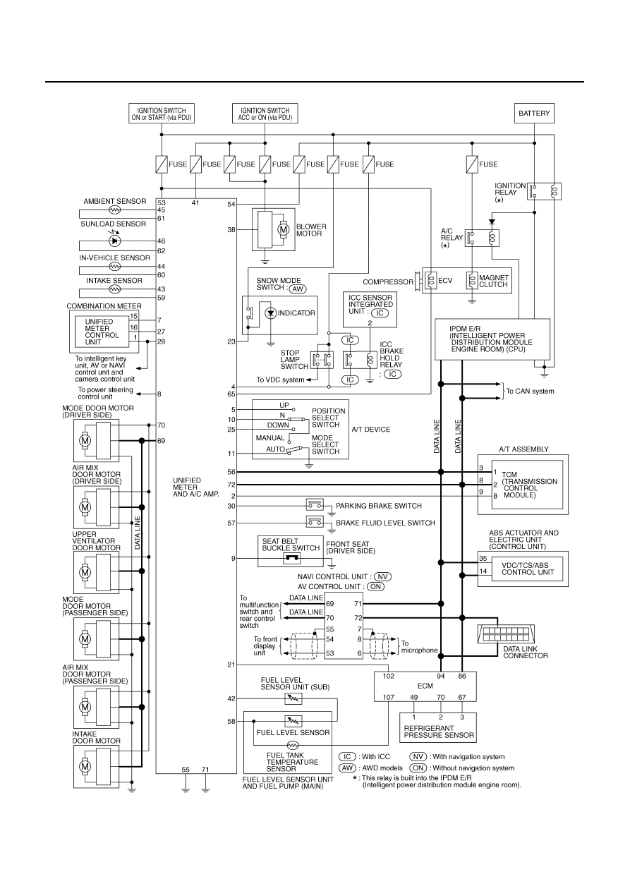
Schematic
NKS003UH
NOTE:
For the further details, refer to descriptions on each system.
TKWT5083E
Нет комментариевНе стесняйтесь поделиться с нами вашим ценным мнением.
Текст