Infiniti M35/M45 Y50. Manual — part 518

DTC P1554 BATTERY CURRENT SENSOR
EC-545
[VQ35DE]
C
D
E
F
G
H
I
J
K
L
M
A
EC
DTC P1554 BATTERY CURRENT SENSOR
PFP:294G0
Component Description
NBS0054C
The power generation voltage variable control enables fuel con-
sumption to be decreased by reducing the engine load which is
caused by the power generation of the generator. The battery cur-
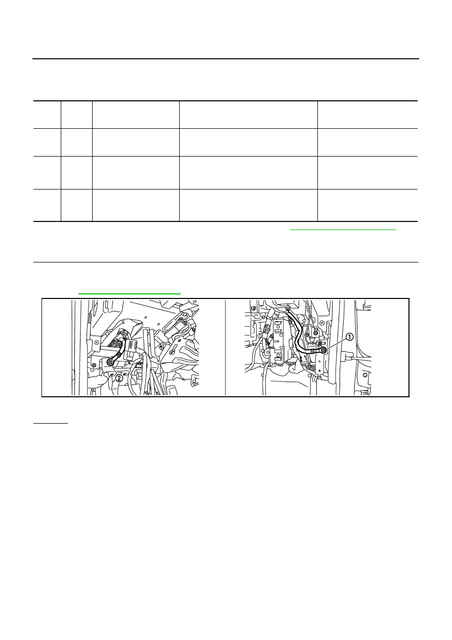
rent sensor (1) is installed to the battery cable at the negative termi-
nal. The sensor measures the charging/discharging current of the
battery. Based on the sensor signal, ECM judges whether or not the
power generation voltage variable control is performed. When per-
forming the power generation voltage variable control, ECM calcu-
lates the target power generation voltage based on the sensor
signal. And ECM sends the calculated value as the power genera-
tion command value to IPDM E/R. For the details of the power gen-
eration voltage variable control, refer to SC section.
CAUTION:
Do not connect the electrical component or the ground wire directly to the battery terminal. The con-
nection causes the malfunction of the power generation voltage variable control, and then the battery
discharge may occur.
CONSULT-II Reference Value in Data Monitor Mode
NBS0054D
Specification data are reference values.
*: Before measuring the terminal voltage, confirm that the battery is fully charged. Refer to
SC-5, "SPECIFIC GRAVITY CHECK"
On Board Diagnosis Logic
NBS0054E
The MIL will not light up for this diagnosis.
NOTE:
If DTC P1554 is displayed with DTC P0643, first perform the trouble diagnosis for DTC P0643. Refer to
EC-486, "DTC P0643 SENSOR POWER SUPPLY"
.
PBIB2685E
MONITOR ITEM
CONDITION
SPECIFICATION
BAT CUR SEN
●
Engine speed: Idle
●
Battery: Fully charged*
●
Selector lever: P or N
●
Air conditioner switch: OFF
●
No load
Approx. 2,600 - 3,500mV
DTC No.
Trouble diagnosis name
DTC detecting condition
Possible cause
P1554
1554
Battery current sensor perfor-
mance
The output voltage of the battery current
sensor is lower than the specified value
while the battery voltage is high enough.
●
Harness or connectors
(The sensor circuit is open or shorted.)
●
Battery current sensor

EC-546
[VQ35DE]
DTC P1554 BATTERY CURRENT SENSOR
Overall Function Check
NBS0054F
Use this procedure to check the overall function of the battery current sensor circuit. During this check, a 1st
trip DTC might not be confirmed.
TESTING CONDITION:
●
Before performing the following procedure, confirm that battery voltage is more than 12.8V at idle.
●
Before performing the following procedure, confirm that all load switches and A/C switch are
turned OFF.
WITH CONSULT-II
1.
Start engine and let it idle.
2.
Select “BAT CUR SEN” in “DATA MONITOR” mode with CON-
SULT-II.
3.
Check “BAT CUR SEN” indication for 10 seconds.
“BAT CUR SEN” should be above 2,300mV at least once.
4.
If NG, go to
EC-548, "Diagnostic Procedure"
WITH GST
1.
Start engine and let it idle.
2.
Check voltage between ECM terminal 71 (battery current sensor
signal) and ground for 10 seconds.
The voltage should be above 2.3V at least once.
3.
If NG, go to
EC-548, "Diagnostic Procedure"
PBIB2615E
PBIB2616E
DTC P1554 BATTERY CURRENT SENSOR
EC-547
[VQ35DE]
C
D
E
F
G
H
I
J
K
L
M
A
EC
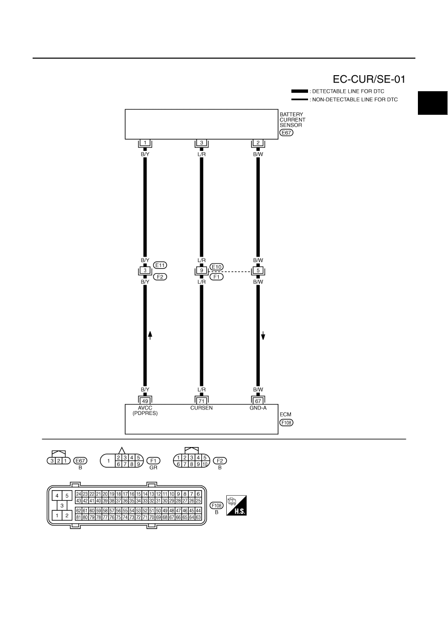
Wiring Diagram
NBS0054G
TBWT0995E
EC-548
[VQ35DE]
DTC P1554 BATTERY CURRENT SENSOR
Specification data are reference values and are measured between each terminal and ground.
CAUTION:
Do not use ECM ground terminals when measuring input/output voltage. Doing so may result in dam-
age to the ECM's transistor. Use a ground other than ECM terminals, such as the ground.
*: Before measuring the terminal voltage, confirm that the battery is fully charged. Refer to
SC-5, "SPECIFIC GRAVITY CHECK"
Diagnostic Procedure
NBS0054H
1.
CHECK GROUND CONNECTIONS
1.
Turn ignition switch OFF.
2.
Loosen and retighten two ground screws on the body.
Refer to
OK or NG
OK
>> GO TO 2.
NG
>> Repair or replace ground connections.
TER-
MINAL
NO.
WIRE
COLOR
ITEM
CONDITION
DATA (DC Voltage)
49
B/Y
Sensor power supply
(Refrigerant pressure sen-
sor, Battery current sensor)
[Ignition switch: ON]
Approximately 5V
67
B/W
Sensor ground
[Engine is running]
●
Warm-up condition
●
Idle speed
Approximately 0V
71
L/R
Battery current sensor
[Engine is running]
●
Battery: Fully charged*
●
Idle speed
Approximately 2.6 - 3.5V
1.
Body ground M70
2.
Body ground M16
PBIB2782E
Нет комментариевНе стесняйтесь поделиться с нами вашим ценным мнением.
Текст