Infiniti M35/M45 Y50. Manual — part 516
DTC P1551, P1552 BATTERY CURRENT SENSOR
EC-537
[VQ35DE]
C
D
E
F
G
H
I
J
K
L
M
A
EC
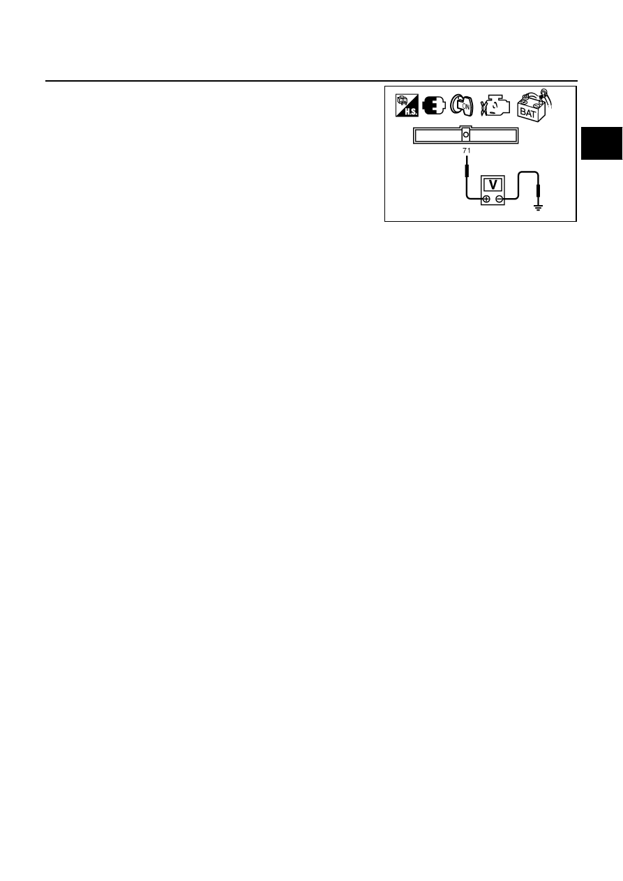
5.
Check voltage between ECM terminal 71 (battery current sensor
signal) and ground.
6.
If NG, replace battery negative cable assembly.
Voltage: Approximately 2.5V
PBIB2617E
EC-538
[VQ35DE]
DTC P1553 BATTERY CURRENT SENSOR
DTC P1553 BATTERY CURRENT SENSOR
PFP:294G0
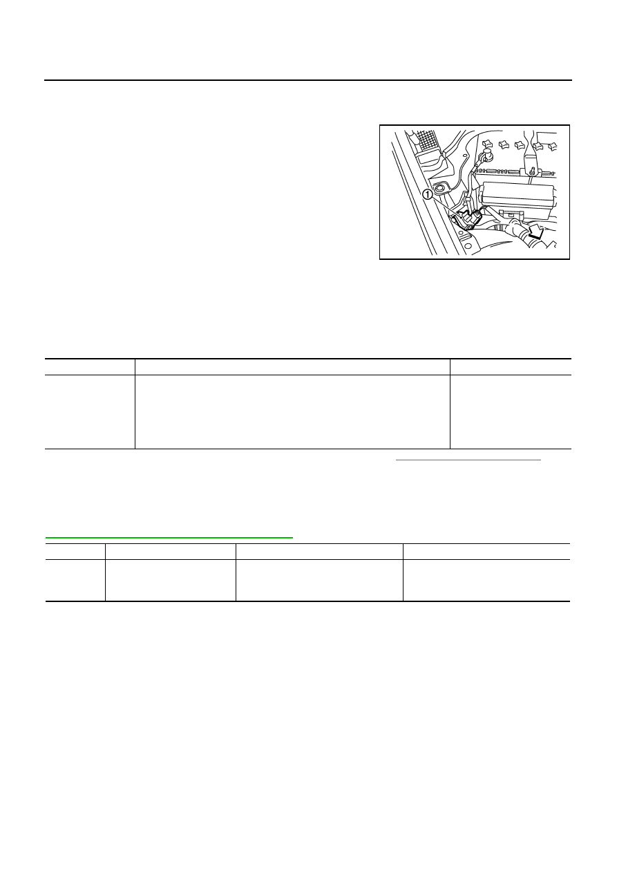
Component Description
NBS00545
The power generation voltage variable control enables fuel con-
sumption to be decreased by reducing the engine load which is
caused by the power generation of the generator. The battery cur-
rent sensor (1) is installed to the battery cable at the negative termi-
nal. The sensor measures the charging/discharging current of the
battery. Based on the sensor signal, ECM judges whether or not the
power generation voltage variable control is performed. When per-
forming the power generation voltage variable control, ECM calcu-
lates the target power generation voltage based on the sensor
signal. And ECM sends the calculated value as the power genera-
tion command value to IPDM E/R. For the details of the power gen-
eration voltage variable control, refer to SC section.
CAUTION:
Do not connect the electrical component or the ground wire directly to the battery terminal. The con-
nection causes the malfunction of the power generation voltage variable control, and then the battery
discharge may occur.
CONSULT-II Reference Value in Data Monitor Mode
NBS00546
Specification data are reference values.
*: Before measuring the terminal voltage, confirm that the battery is fully charged. Refer to
SC-5, "SPECIFIC GRAVITY CHECK"
On Board Diagnosis Logic
NBS00547
The MIL will not light up for this diagnosis.
NOTE:
If DTC P1553 is displayed with DTC P0643, first perform the trouble diagnosis for DTC P0643. Refer to
EC-486, "DTC P0643 SENSOR POWER SUPPLY"
PBIB2685E
MONITOR ITEM
CONDITION
SPECIFICATION
BAT CUR SEN
●
Engine speed: Idle
●
Battery: Fully charged*
●
Selector lever: P or N
●
Air conditioner switch: OFF
●
No load
Approx. 2,600 - 3,500mV
DTC No.
Trouble diagnosis name
DTC detecting condition
Possible cause
P1553
1553
Battery current sensor perfor-
mance
The signal voltage transmitted from the
sensor to ECM is higher than the amount
of the maximum power generation.
●
Harness or connectors
(The sensor circuit is open or shorted.)
●
Battery current sensor

DTC P1553 BATTERY CURRENT SENSOR
EC-539
[VQ35DE]
C
D
E
F
G
H
I
J
K
L
M
A
EC
DTC Confirmation Procedure
NBS00548
If DTC Confirmation Procedure has been previously conducted, always turn ignition switch OFF and wait at
least 10 seconds before conducting the next test.
TESTING CONDITION:
Before performing the following procedure, confirm that battery voltage is more than 8V at idle.
WITH CONSULT-II
1.
Turn ignition switch ON.
2.
Select “DATA MONITOR” mode with CONSULT-II.
3.
Start engine and wait at least 10 seconds.
4.
If 1st trip DTC is detected, go to
EC-541, "Diagnostic Procedure"
.
WITH GST
Follow the procedure “WITH CONSULT-II” above.
SEF058Y
EC-540
[VQ35DE]
DTC P1553 BATTERY CURRENT SENSOR
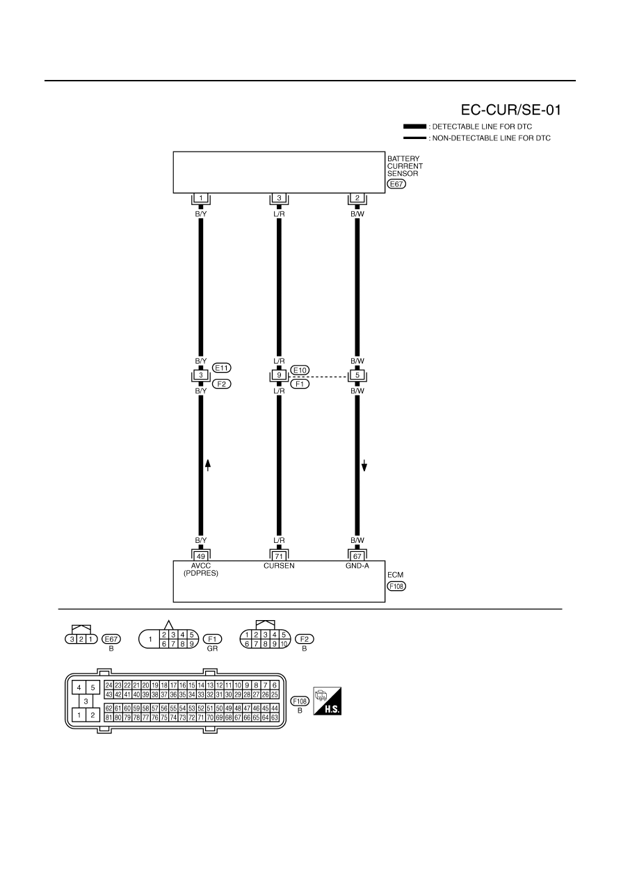
Wiring Diagram
NBS00549
TBWT0995E
Нет комментариевНе стесняйтесь поделиться с нами вашим ценным мнением.
Текст