Infiniti M35/M45 Y50. Manual — part 519

DTC P1554 BATTERY CURRENT SENSOR
EC-549
[VQ35DE]
C
D
E
F
G
H
I
J
K
L
M
A
EC
2.
CHECK BATTERY CURRENT SENSOR POWER SUPPLY CIRCUIT
1.
Disconnect battery current sensor harness connector.
2.
Turn ignition switch ON.
3.
Check voltage between battery current sensor terminal 1 and
ground with CONSULT-II or tester.
OK or NG
OK
>> GO TO 4.
NG
>> GO TO 3.
3.
DETECT MALFUNCTIONING PART
Check the following.
●
Harness connectors E11, F2
●
Harness for open or short between battery current sensor and ECM
>> Repair open circuit or short to ground or short to power in harness or connectors.
4.
CHECK BATTERY CURRENT SENSOR GROUND CIRCUIT FOR OPEN AND SHORT
1.
Turn ignition switch OFF.
2.
Disconnect ECM harness connector.
3.
Check harness continuity between battery current sensor terminal 2 and ECM terminal 67.
Refer to Wiring Diagram.
4.
Also check harness for short to ground and short to power.
OK or NG
OK
>> GO TO 6.
NG
>> GO TO 5.
5.
DETECT MALFUNCTIONING PART
Check the following.
●
Harness connectors E10, F1
●
Harness for open or short between battery current sensor and ECM
>> Repair open circuit or short to ground or short to power in harness or connectors.
PBIB2685E
Voltage: Approximately 5V
PBIA9891J
Continuity should exist.
EC-550
[VQ35DE]
DTC P1554 BATTERY CURRENT SENSOR
6.
CHECK BATTERY CURRENT SENSOR INPUT SIGNAL CIRCUIT FOR OPEN AND SHORT
1.
Check harness continuity between battery current sensor terminal 3 and ECM terminal 71.
Refer to Wiring Diagram.
2.
Also check harness for short to ground and short to power.
OK or NG
OK
>> GO TO 8.
NG
>> GO TO 7.
7.
DETECT MALFUNCTIONING PART
Check the following.
●
Harness connectors E10, F1
●
Harness for open or short between battery current sensor and ECM
>> Repair open circuit or short to ground or short to power in harness or connectors.
8.
CHECK BATTERY CURRENT SENSOR
Refer to
EC-550, "Component Inspection"
OK or NG
OK
>> GO TO 9.
NG
>> Replace battery negative cable assembly.
9.
CHECK INTERMITTENT INCIDENT
Refer to
EC-153, "TROUBLE DIAGNOSIS FOR INTERMITTENT INCIDENT"
.
>> INSPECTION END
Component Inspection
NBS0054I
BATTERY CURRENT SENSOR
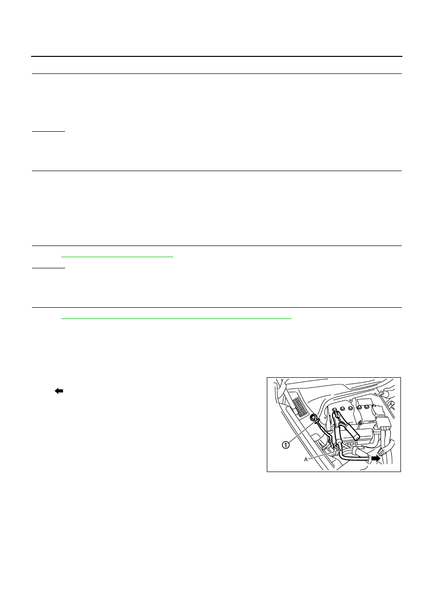
1.
Reconnect harness connectors disconnected.
2.
Disconnect battery negative cable (1).
●
: To body ground
3.
Install jumper cable (A) between battery negative terminal and
body ground.
4.
Turn ignition switch ON.
Continuity should exist.
PBIB2724E

DTC P1554 BATTERY CURRENT SENSOR
EC-551
[VQ35DE]
C
D
E
F
G
H
I
J
K
L
M
A
EC
5.
Check voltage between ECM terminal 71 (battery current sensor
signal) and ground.
6.
If NG, replace battery negative cable assembly.
Voltage: Approximately 2.5V
PBIB2617E

EC-552
[VQ35DE]
DTC P1564 ICC STEERING SWITCH
DTC P1564 ICC STEERING SWITCH
PFP:25551
Component Description
NBS0054J
ICC steering switch has variant values of electrical resistance for each button. ECM reads voltage variation of
switch, and determines which button is operated.
Refer to
for the ICC function.
CONSULT-II Reference Value in Data Monitor Mode
NBS0054K
Specification data are reference values.
On Board Diagnosis Logic
NBS0054L
This self-diagnosis has the one trip detection logic.
The MIL will not light up for this diagnosis.
NOTE:
If DTC P1564 is displayed with DTC P0605, first perform the trouble diagnosis for DTC P0605. Refer to
1.
ICC steering switch
2.
RESUME/ACCELERATE switch
3.
SET/COAST switch
4.
CANCEL switch
5.
DISTANCE switch
6.
MAIN switch
PBIB2709E
MONITOR ITEM
CONDITION
SPECIFICATION
MAIN SW
●
Ignition switch: ON
MAIN switch: Pressed
ON
MAIN switch: Released
OFF
CANCEL SW
●
Ignition switch: ON
CANCEL switch: Pressed
ON
CANCEL switch: Released
OFF
RESUME/ACC SW
●
Ignition switch: ON
RESUME/ACCELERATE switch:
Pressed
ON
RESUME/ACCELERATE switch:
Released
OFF
SET SW
●
Ignition switch: ON
SET/COAST switch: Pressed
ON
SET/COAST switch: Released
OFF
DIST SW
●
Ignition switch: ON
DISTANCE switch: Pressed
ON
DISTANCE switch: Released
OFF
DTC No.
Trouble diagnosis
name
DTC detecting condition
Possible cause
P1564
1564
ICC steering switch
●
An excessively high voltage signal from the
ICC steering switch is sent to ECM.
●
ECM detects that input signal from the ICC
steering switch is out of the specified range.
●
ECM detects that the ICC steering switch is
stuck ON.
●
Harness or connectors
(The switch circuit is open or shorted.)
●
ICC steering switch
●
ECM
Нет комментариевНе стесняйтесь поделиться с нами вашим ценным мнением.
Текст