Infiniti M35/M45 Y50. Manual — part 910
ACTIVE AFS
LT-185
C
D
E
F
G
H
I
J
L
M
A
B
LT
CHECK HEIGHT SENSOR SIGNAL AND AIMING MOTOR DRIVE SIGNAL
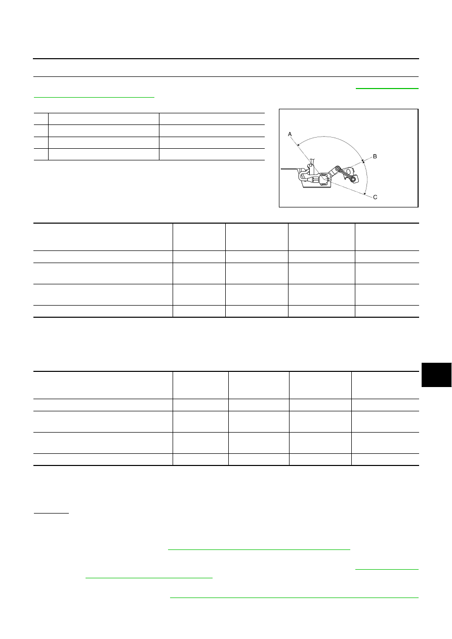
Remove height sensor link bracket mounting nuts (rear stabilizer side). For details, refer to
and Installation of Height Sensor"
. Change sensor angle from the basic point of sensor angle 0
°
(standard
position) and check “HI SEN OTP RR” and “LEV ACTR VLTG” of “Data Monitor”.
With 18-inch wheel
NOTE:
1. Reference value. The value can be different from that of sensor angle and HI SEN OTP RR of maximum/minimum angle of auto
aiming operation depending on LEVELIZER ADJUSTMENT state.
2. Reference value. Approx.
−
1.5 V from the LEVELIZER ADJUSTMENT value.
With 19-inch wheel
NOTE:
1. Reference value. The value can be different from that of sensor angle and HI SEN OTP RR of maximum/minimum angle of auto
aiming operation depending on LEVELIZER ADJUSTMENT state.
2. Reference value. Approx.
−
1.2 V from LEVELIZER ADJUSTMENT value.
OK or NG
OK
>> Auto aiming operation function is normal.
NG
>>
●
When approx. 4.5 V or 0.5 V is not displayed on “HI SEN OTP RR” screen with sensor angle
approx. 45
°
or
−
45
°
, check connector for connection, bend and loose fit. If it is normal, replace
height sensor. Refer to
LT-193, "Removal and Installation of Height Sensor"
●
When “HI SEN OTP RR” value is normal but “LEV ACTR VLTG” value differs from maximum/
minimum angle of auto aiming operation, replace AFS control unit. Refer to
and Installation of AFS Control Unit"
●
When “LEV ACTR VLTG” value is normal but operation range is irregular, check aiming motor
system circuit. Refer to
LT-188, "Auto Aiming Does Not Operate (Check Aiming Motor System
Sensor angle
Vehicle height
A
Approx. –103
°
(Link stopper angle)
Low side
B
0
°
(Standard position)
Unloaded vehicle position
C
Approx. 46
°
(Link stopper angle)
High side
SKIB4689E
Sensor angle
“HI SEN OTP RR”
“LEV ACTR VLTG”
Light axis range at
10 m (394.7 in) off
(Reference value)
Limit value of vehicle height (high side)
Approx. 45
°
Approx. 4.5 V
Approx. 70.0%
—
Maximum angle of auto aiming operation
NOTE1
(Unloaded vehicle position)
Approx. 0
°
Approx. 2.5 V
Approx. 70.0%
0
Minimum angle of auto aiming operation
NOTE1
(Maximum laden condition)
Approx.
−
35
°
Approx. 1.0 V
NOTE2
Approx. 38.0%
Approx. 200 mm
(7.9 in)
Limit value of vehicle height (low side)
Approx.
−
45
°
Approx. 0.5 V
Approx. 38.0%
—
Sensor angle
“HI SEN OTP RR”
“LEV ACTR VLTG”
Light axis range at
10m (394.7 in) off
(Reference value)
Limit value of vehicle height (high side)
Approx. 45
°
Approx. 4.5 V
Approx. 70.0%
—
Maximum angle of auto aiming operation
NOTE1
(Unloaded vehicle position)
Approx. 0
°
Approx. 2.5 V
Approx. 70.0%
0
Minimum angle of auto aiming operation
NOTE1
(Maximum laden condition)
Approx.
−
27
°
Approx. 1.3
NOTE2
Approx. 41.8%
Approx. 180 mm
(7.1 in)
Limit value of vehicle height (low side)
Approx.
−
45
°
Approx. 0.5 V
Approx. 41.8%
—
LT-186
ACTIVE AFS
AFS Switch Does Not Operate
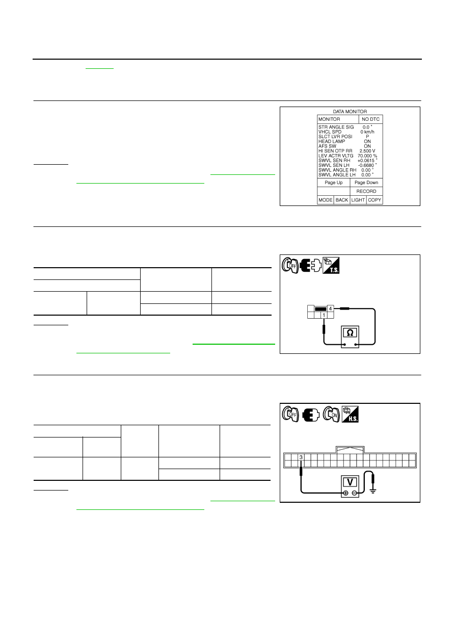
NKS003QU
1.
CHECK AFS SWITCH SIGNAL 1
1.
Turn ignition switch ON.
2.
Select “ADAPTIVE LIGHT” on CONSULT-II. Select “DATA
MONITOR” on “SELECT DIAG MODE” screen.
3.
Make sure that “AFS SW” turn ON-OFF according to AFS switch
operation.
OK or NG
OK
>> Replace AFS control unit. Refer to
and Installation of AFS Control Unit"
.
NG
>> GO TO 2.
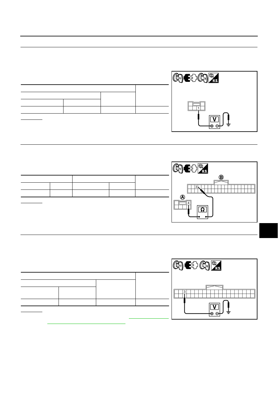
2.
CHECK AFS SWITCH
1.
Turn ignition switch OFF.
2.
Disconnect AFS switch connector.
3.
Check continuity AFS switch.
OK or NG
OK
>> GO TO 3.
NG
>> Replace AFS switch. Refer to
3.
CHECK AFS SWITCH SIGNAL 2
1.
Connect AFS switch connector.
2.
Turn ignition switch ON.
3.
Check voltage between AFS control unit harness connector and
ground according to AFS switch operation.
OK or NG
OK
>> Replace AFS control unit. Refer to
and Installation of AFS Control Unit"
.
NG
>>
●
If voltage is approx. 0 V and stays unchanged, GO TO 4.
●
If voltage is battery voltage and stays unchanged, GO TO 6.
SKIB4793E
AFS switch
Condition
Continuity
Terminal
1
4
AFS switch is ON.
No
AFS switch is OFF.
Yes
PKIC0684E
(+)
(-)
Condition
Voltage
(Approx.)
AFS control
unit connector
Terminal
F110
3
Ground
AFS switch is ON.
0 V
AFS switch is OFF.
Battery voltage
PKIC0683E
ACTIVE AFS
LT-187
C
D
E
F
G
H
I
J
L
M
A
B
LT
4.
CHECK AFS SWITCH POWER SUPPLY CIRCUIT
1.
Turn ignition switch OFF.
2.
Disconnect AFS switch connector.
3.
Turn ignition switch ON.
4.
Check voltage between AFS switch harness connector and
ground.
OK or NG
OK
>> GO TO 5.
NG
>> Repair harness or connector.
5.
CHECK AFS SWITCH CIRCUIT
1.
Turn ignition switch OFF.
2.
Disconnect AFS control unit connector.
3.
Check continuity between AFS switch harness connector (A)
and AFS control unit harness connector (B).
OK or NG
OK
>> Check connector for connection, bend and loose fit.
NG
>> Repair harness or connector.
6.
CHECK AFS SWITCH CIRCUIT (IGN POWER SUPPLY SHORT CIRCUIT)
1.
Turn ignition switch OFF.
2.
Disconnect AFS control unit connector and AFS switch connector.
3.
Turn ignition switch ON.
4.
Check voltage between AFS control unit harness connector and
ground.
OK or NG
OK
>> Replace AFS control unit. Refer to
and Installation of AFS Control Unit"
NG
>> Repair harness or connector.
Terminals
Voltage
(Approx.)
(+)
(-)
AFS switch connector
Terminal
M96
1
Ground
Battery voltage
PKIC0685E
A
B
Continuity
Connector
Terminal Connector
Terminal
M96
4
F110
3
Yes
PKIC0686E
Terminals
Voltage
(Approx.)
(+)
(-)
AFS control unit
connector
Terminal
F110
3
Ground
Battery voltage
SKIB4992E
LT-188
ACTIVE AFS
Auto Aiming Does Not Operate (Check Aiming Motor System Circuit)
NKS003QV
1.
CHECK AIMING MOTOR
1.
Start engine and turn lighting switch to 2ND position.
2.
Select “ADAPTIVE LIGHT” on CONSULT-II. Select “ACTIVE
TEST” on “SELECT DIAG MODE” screen.
3.
Select “LEVELIZER TEST” on “SELECT TEST ITEM” screen.
4.
Touch “ORIGIN” or “PEAK” screen.
5.
Make sure of aiming motor operation.
OK or NG
OK
>> Replace AFS control unit. Refer to
and Installation of AFS Control Unit"
.
NG
>> GO TO 2.
2.
CHECK AIMING MOTOR DRIVE SIGNAL
1.
Touch “ORIGIN” or “PEAK” screen in “LEVELIZER TEST”.
2.
Check voltage between AFS control unit harness connector and
ground.
OK or NG
OK
>> GO TO 3.
NG
>> GO TO 6.
3.
CHECK AIMING MOTOR DRIVE SIGNAL CIRCUIT
1.
Turn ignition switch OFF.
2.
Disconnect front combination lamp RH and LH connector.
3.
Start engine.
4.
Touch “ORIGIN” or “PEAK” screen in “LEVELIZER TEST”.
5.
Check voltage between front combination lamp (LH and RH)
harness connector and ground.
OK or NG
OK
>> GO TO 4.
NG
>> Repair harness or connector.
SKIB4796E
(+)
(-)
Condition
Voltage
(Approx.)
AFS control unit
connector
Terminal
RH
F110
19
Ground
ORIGIN
10.6 V
PEAK
1.9 V
LH
40
ORIGIN
10.6 V
PEAK
1.9 V
PKIC0687E
(+)
(-)
Condition
Voltage
(Approx.)
Front combination
lamp connector
Terminal
RH
E70
12
Ground
ORIGIN
10.6 V
PEAK
1.9 V
LH
E71
12
ORIGIN
10.6 V
PEAK
1.9 V
PKIC0688E
Нет комментариевНе стесняйтесь поделиться с нами вашим ценным мнением.
Текст