Infiniti M35/M45 Y50. Manual — part 908
ACTIVE AFS
LT-177
C
D
E
F
G
H
I
J
L
M
A
B
LT
7.
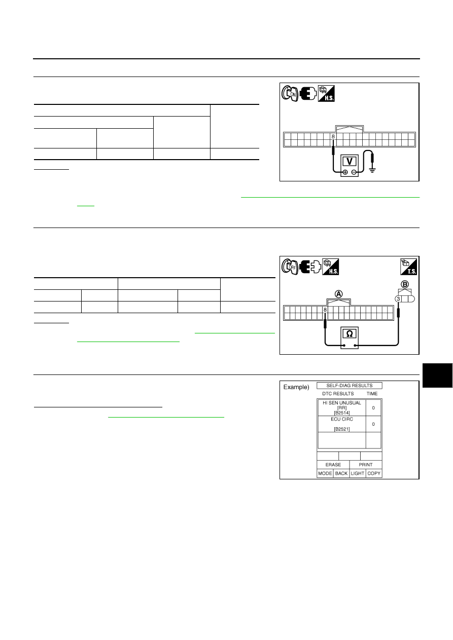
CHECK HEIGHT SENSOR GROUND
Check voltage between AFS control unit harness connector and
ground.
OK or NG
OK
>> GO TO 8.
NG
>> Check connector for connection, bend and loose fit. If it
is normal, replace AFS control unit. Refer to
LT-192, "Removal and Installation of AFS Control
8.
CHECK HEIGHT SENSOR GROUND CIRCUIT
1.
Turn ignition switch OFF.
2.
Disconnect AFS control unit connector and height sensor connector.
3.
Check continuity between AFS control unit harness connector
(A) and height sensor harness connector (B).
OK or NG
OK
>> Replace height sensor. Refer to
Installation of Height Sensor"
.
NG
>> Repair harness or connector.
9.
CHECK DIAGNOSIS RESULT
Select “ADAPTIVE LIGHT” on CONSULT-II. Select “SELF-DIAG
RESULTS” on “SELECT DIAG MODE” screen.
Is DTC B2521 ECU CIRC detected?
YES
>> Refer to
NO
>> GO TO 10.
Terminals
Voltage
(Approx.)
(+)
(-)
AFS control unit
connector
Terminal
F110
8
Ground
0 V
PKIC0671E
A
B
Continuity
Connector
Terminal Connector
Terminal
F110
8
B468
3
Yes
PKIC0672E
SKIB4973E
LT-178
ACTIVE AFS
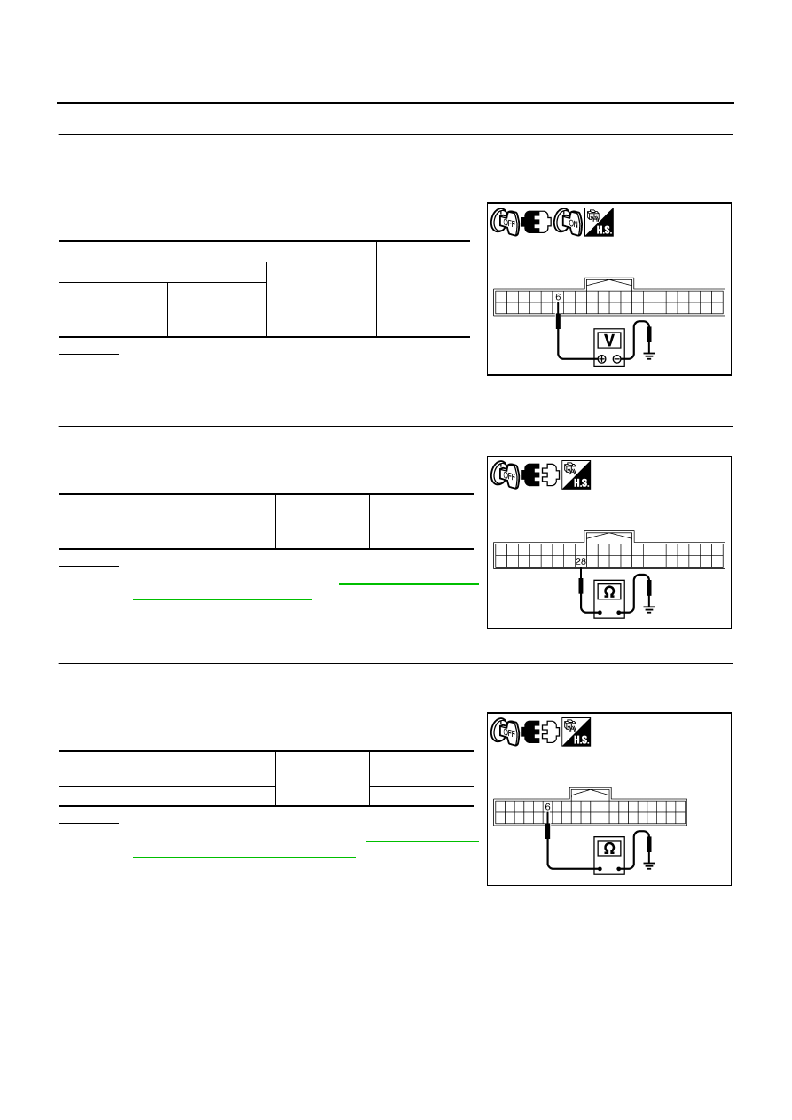
10.
CHECK HEIGHT SENSOR POWER SUPPLY CIRCUIT
1.
Turn ignition switch OFF.
2.
Disconnect height sensor connector.
3.
Turn ignition switch ON.
4.
Check voltage between AFS control unit harness connector and
ground.
OK or NG
OK
>> GO TO 11.
NG
>> GO TO 12.
11.
CHECK HEIGHT SENSOR SIGNAL CIRCUIT (SHORT CIRCUIT)
1.
Disconnect AFS control unit connector.
2.
Check continuity between AFS control unit harness connector
and ground.
OK or NG
OK
>> Replace height sensor. Refer to
Installation of Height Sensor"
NG
>> Repair harness or connector.
12.
CHECK HEIGHT SENSOR POWER SUPPLY CIRCUIT (SHORT CIRCUIT)
1.
Turn ignition switch OFF.
2.
Disconnect AFS control unit connector.
3.
Check continuity between AFS control unit harness connector
and ground.
OK or NG
OK
>> Replace AFS control unit. Refer to
and Installation of AFS Control Unit"
.
NG
>> Repair harness or connector.
Terminals
Voltage
(Approx.)
(+)
(-)
AFS control unit
connector
Terminal
F110
6
Ground
4.0 - 6.0 V
PKIC0673E
AFS control unit
connector
Terminal
Ground
Continuity
F110
28
No
SKIB4970E
AFS control unit
connector
Terminal
Ground
Continuity
F110
6
No
PKIC0674E
ACTIVE AFS
LT-179
C
D
E
F
G
H
I
J
L
M
A
B
LT
DTC B2521 ECU CIRC
NKS003QR
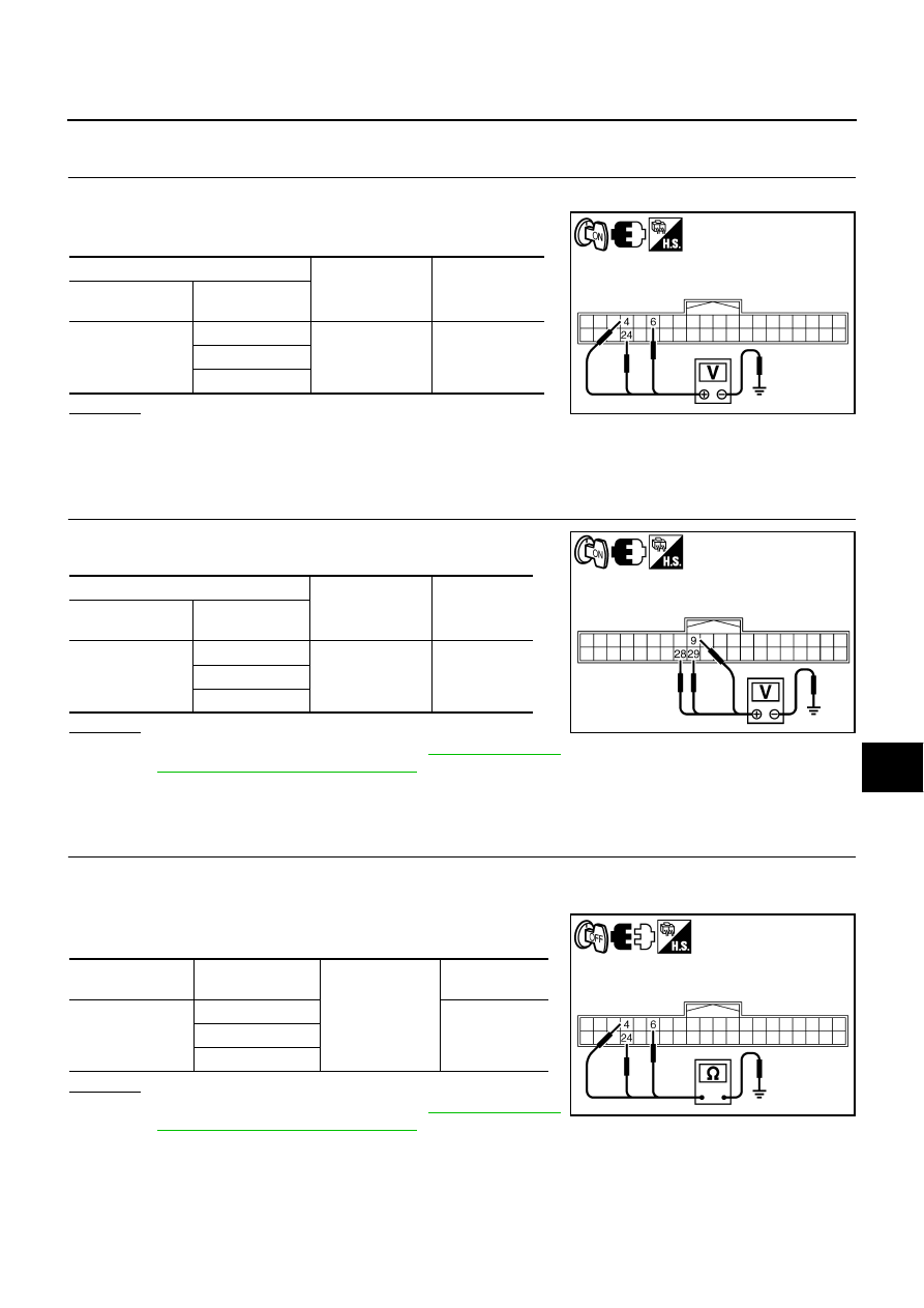
1.
CHECK SENSOR POWER SUPPLY
1.
Turn ignition switch ON.
2.
Check voltage between AFS control unit harness connector and
ground.
OK or NG
OK
>> GO TO 2.
NG
>>
●
If voltage is less than approx. 4 V, GO TO 3.
●
If voltage is more than approx. 6 V, GO TO 4.
2.
CHECK SENSOR SIGNAL
Check voltage between AFS control unit harness connector and
ground.
OK or NG
OK
>> Replace AFS control unit. Refer to
and Installation of AFS Control Unit"
NG
>>
●
If voltage is less than approx. 0.25 V, GO TO 5.
●
If voltage is more than approx. 4.75 V, GO TO 6.
3.
CHECK SENSOR POWER SUPPLY CIRCUIT (GROUND SHORT CIRCUIT)
1.
Turn ignition switch OFF.
2.
Disconnect AFS control unit connector.
3.
Check continuity between AFS control unit harness connector
and ground.
OK or NG
OK
>> Replace AFS control unit. Refer to
and Installation of AFS Control Unit"
NG
>> GO TO 7.
(+)
(-)
Voltage
(Approx.)
AFS control unit
connector
Terminal
F110
4
Ground
4.0 - 6.0 V
6
24
PKIC0675E
(+)
(-)
Voltage
(Approx.)
AFS control unit
connector
Terminal
F110
9
Ground
0.25 - 4.75 V
28
29
PKIC0676E
AFS control unit
connector
Terminal
Ground
Continuity
F110
4
No
6
24
PKIC0677E

LT-180
ACTIVE AFS
4.
CHECK SENSOR POWER SUPPLY CIRCUIT (IGN POWER SUPPLY SHORT CIRCUIT)
1.
Turn ignition switch OFF.
2.
Disconnect AFS control unit connector.
3.
Turn ignition switch ON.
4.
Check voltage between AFS control unit harness connector and
ground.
OK or NG
OK
>> Replace AFS control unit. Refer to
and Installation of AFS Control Unit"
.
NG
>> GO TO 8.
5.
CHECK SENSOR SIGNAL CIRCUIT (GROUND SHORT CIRCUIT)
1.
Turn ignition switch OFF.
2.
Disconnect AFS control unit connector.
3.
Check continuity between AFS control unit harness connector
and ground.
OK or NG
OK
>> Replace AFS control unit. Refer to
and Installation of AFS Control Unit"
.
NG
>> GO TO 7.
6.
CHECK SENSOR SIGNAL CIRCUIT (IGN POWER SUPPLY SHORT CIRCUIT)
1.
Turn ignition switch OFF.
2.
Disconnect AFS control unit connector.
3.
Turn ignition switch ON.
4.
Check voltage between AFS control unit harness connector and
ground.
OK or NG
OK
>> Replace AFS control unit. Refer to
and Installation of AFS Control Unit"
.
NG
>> GO TO 8.
(+)
(-)
Voltage
(Approx.)
AFS control
unit connector
Terminal
F110
4
Ground
0 V
6
24
PKIC0678E
AFS control unit
connector
Terminal
Ground
Continuity
F110
9
No
28
29
PKIC0679E
(+)
(-)
Voltage
(Approx.)
AFS control unit
connector
Terminal
F110
9
Ground
0 V
8
29
PKIC0680E
Нет комментариевНе стесняйтесь поделиться с нами вашим ценным мнением.
Текст