Infiniti M35/M45 Y50. Manual — part 911
ACTIVE AFS
LT-189
C
D
E
F
G
H
I
J
L
M
A
B
LT
4.
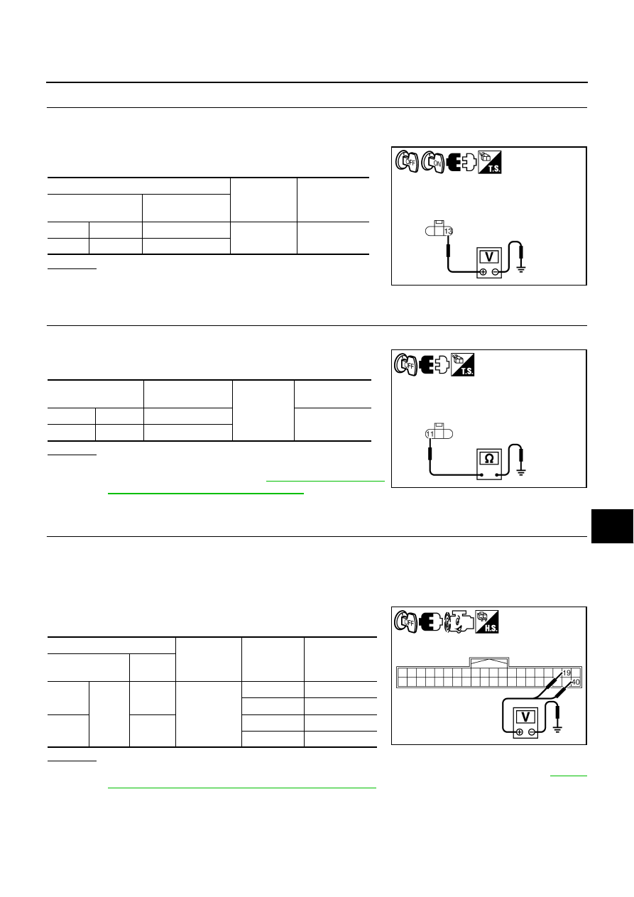
CHECK AIMING MOTOR POWER SUPPLY
1.
Turn ignition switch OFF.
2.
Turn ignition switch ON.
3.
Check voltage between front combination lamp (RH and LH)
harness connector and ground.
OK or NG
OK
>> GO TO 5.
NG
>> Repair harness or connector.
5.
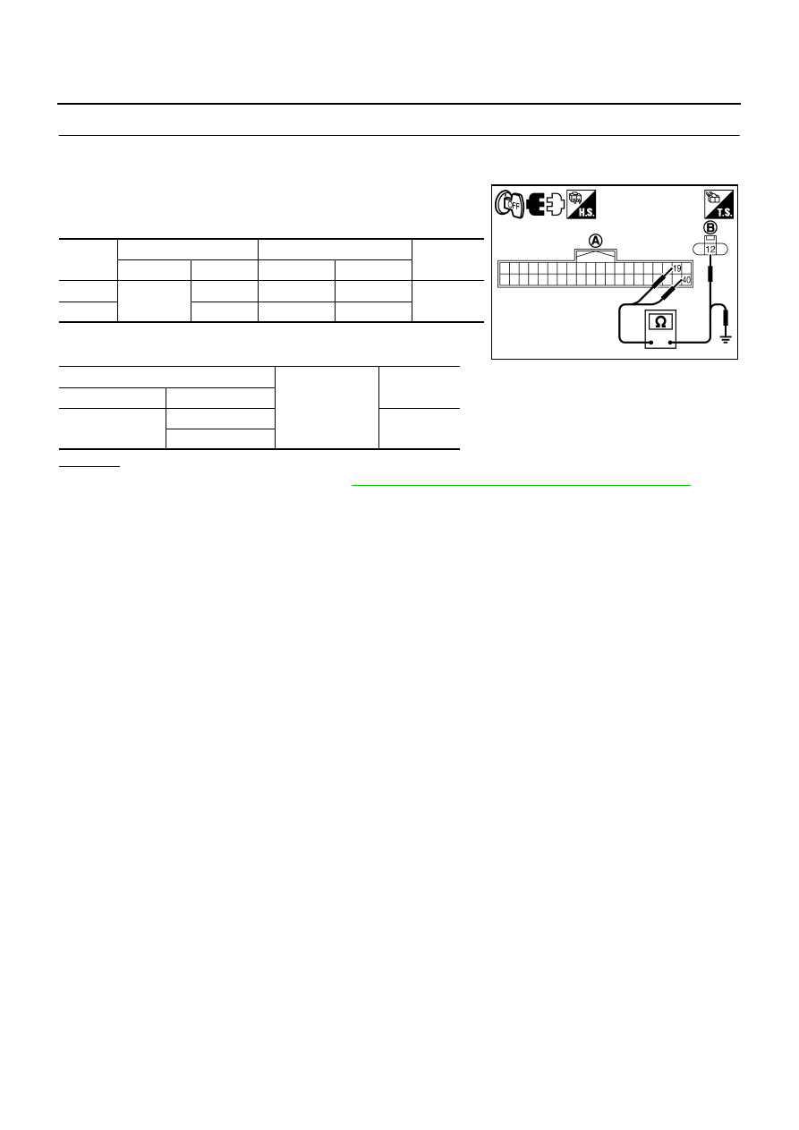
CHECK AIMING MOTOR GROUND
1.
Turn ignition switch OFF.
2.
Check continuity between front combination lamp (RH and LH)
harness connector and ground.
OK or NG
OK
>> Replace front combination lamp RH and LH (aiming
Installation of Front Combination Lamp"
NG
>> Repair harness or connector.
6.
CHECK AIMING MOTOR DRIVE SIGNAL CIRCUIT
1.
Turn ignition switch OFF.
2.
Disconnect front combination lamp RH and LH connector.
3.
Start engine.
4.
Touch “ORIGIN” or “PEAK” screen in “LEVELIZER TEST”.
5.
Check voltage between AFS control unit harness connector and
ground.
OK or NG
OK
>> Replace front combination lamp RH and LH (aiming motor malfunction). Refer to
"Removal and Installation of Front Combination Lamp"
NG
>> GO TO 7.
(+)
(-)
Voltage
(Approx.)
Front combination
lamp connector
Terminal
RH
E70
13
Ground
Battery voltage
LH
E71
13
PKIC0689E
Front combination
lamp connector
Terminal
Ground
Continuity
RH
E70
11
Yes
LH
E71
11
PKIC0690E
(+)
(-)
Condition
Voltage
(Approx.)
AFS control unit
connector
Terminal
RH
F110
19
Ground
ORIGIN
10.6 V
PEAK
1.9 V
LH
40
ORIGIN
10.6 V
PEAK
1.9 V
SKIB4960E
LT-190
ACTIVE AFS
7.
CHECK AIMING MOTOR DRIVE SIGNAL CIRCUIT
1.
Turn ignition switch OFF.
2.
Disconnect AFS control unit connector.
3.
Check continuity between AFS control unit harness connector
(A) and front combination lamp (LH or RH) harness connector
(B).
4.
Check continuity between AFS control unit harness connector
(A) and ground.
OK or NG
OK
>> Replace AFS control unit. Refer to
LT-192, "Removal and Installation of AFS Control Unit"
NG
>> Repair harness or connector.
Circuit
A
B
Continuity
Connector
Terminal
Connector
Terminal
RH
F110
19
E70
12
Yes
LH
40
E71
12
A
Ground
Continuity
Connector
Terminal
F110
19
No
40
PKIC0691E
ACTIVE AFS
LT-191
C
D
E
F
G
H
I
J
L
M
A
B
LT
AFS OFF Indicator Does Not Operate
NKS003QW
1.
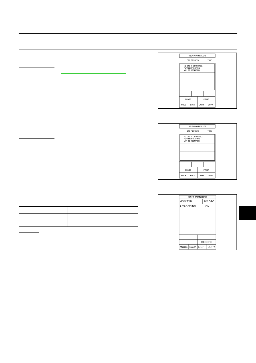
CHECK DIAGNOSIS RESULT (AFS CONTROL UNIT)
Select “ADAPTIVE LIGHT” on CONSULT-II. Select “SELF-DIAG
RESULTS” on “SELECT DIAG MODE” screen.
Is DTC detected?
YES
>> Refer to
.
NO
>> GO TO 2.
2.
CHECK DIAGNOSIS RESULT (UNIFIED METER AND A/C AMP.)
Select “METER A/C AMP” on CONSULT-II. Select “SELF-DIAG
RESULTS” on “SELECT DIAG MODE” screen.
Is DTC detected?
YES
>> Refer to
.
NO
>> GO TO 3.
3.
CHECK AFS OFF INDICATOR SIGNAL (UNIFIED METER AND A/C AMP.)
Check “AFS OFF IND” in “Data Monitor” according to AFS switch
operation.
OK or NG
OK
>> Replace combination meter.
NG
>> Replace unified meter and A/C amp.
Removal and Installation of Steering Angle Sensor
NKS003QX
Refer to
BRC-60, "STEERING ANGLE SENSOR"
Removal and Installation of Front Combination Lamp
NKS003QY
Refer to
LT-75, "Removal and Installation"
PKIA6866E
PKIA6866E
Condition
“AFS OFF IND”
AFS switch is OFF.
ON
AFS switch is ON.
OFF
SKIB4971E
LT-192
ACTIVE AFS
Removal and Installation of AFS Control Unit
NKS003QZ
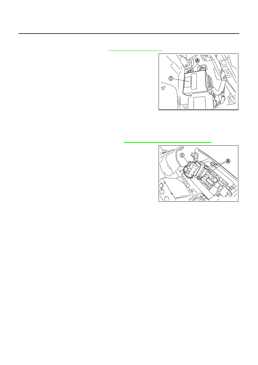
REMOVAL
1.
Remove dash side finisher RH. Refer to
2.
Remove screw (A).
3.
Disconnect AFS control unit connector.
4.
Remove AFS control unit (1).
INSTALLATION
Installation is the reverse order of removal.
Removal and Installation of AFS Switch
NKS003R0
REMOVAL
1.
Remove instrument lower driver panel. Refer to
IP-10, "INSTRUMENT PANEL ASSEMBLY"
.
2.
Press AFS switch fixing pawls (A) and remove unit (1) from
instrument lower driver panel.
INSTALLATION
Installation is the reverse order of removal.
SKIB4766E
SKIB4768E
Нет комментариевНе стесняйтесь поделиться с нами вашим ценным мнением.
Текст