Infiniti M35/M45 Y50. Manual — part 652
DTC P0335 CKP SENSOR (POS)
EC-1081
[VK45DE]
C
D
E
F
G
H
I
J
K
L
M
A
EC
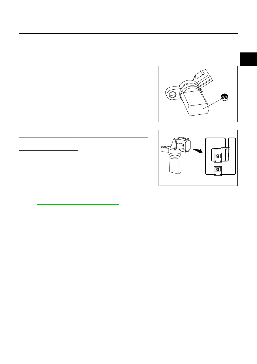
Component Inspection
NBS005GJ
CRANKSHAFT POSITION SENSOR (POS)
1.
Loosen the fixing bolt of the sensor.
2.
Disconnect crankshaft position sensor (POS) harness connector.
3.
Remove the sensor.
4.
Visually check the sensor for chipping.
5.
Check resistance as shown in the figure.
Removal and Installation
NBS005GK
CRANKSHAFT POSITION SENSOR (POS)
Refer to
EM-187, "OIL PAN AND OIL STRAINER"
.
PBIB0563E
Terminal No. (Polarity)
Resistance
Ω
[at 25
°
C (77
°
F)]
1 (+) - 2 (-)
Except 0 or
∞
1 (+) - 3 (-)
2 (+) - 3 (-)
PBIB0564E
EC-1082
[VK45DE]
DTC P0340 CAMSHAFT POSITION (CMP) SENSOR (PHASE)
DTC P0340 CAMSHAFT POSITION (CMP) SENSOR (PHASE)
PFP:23731
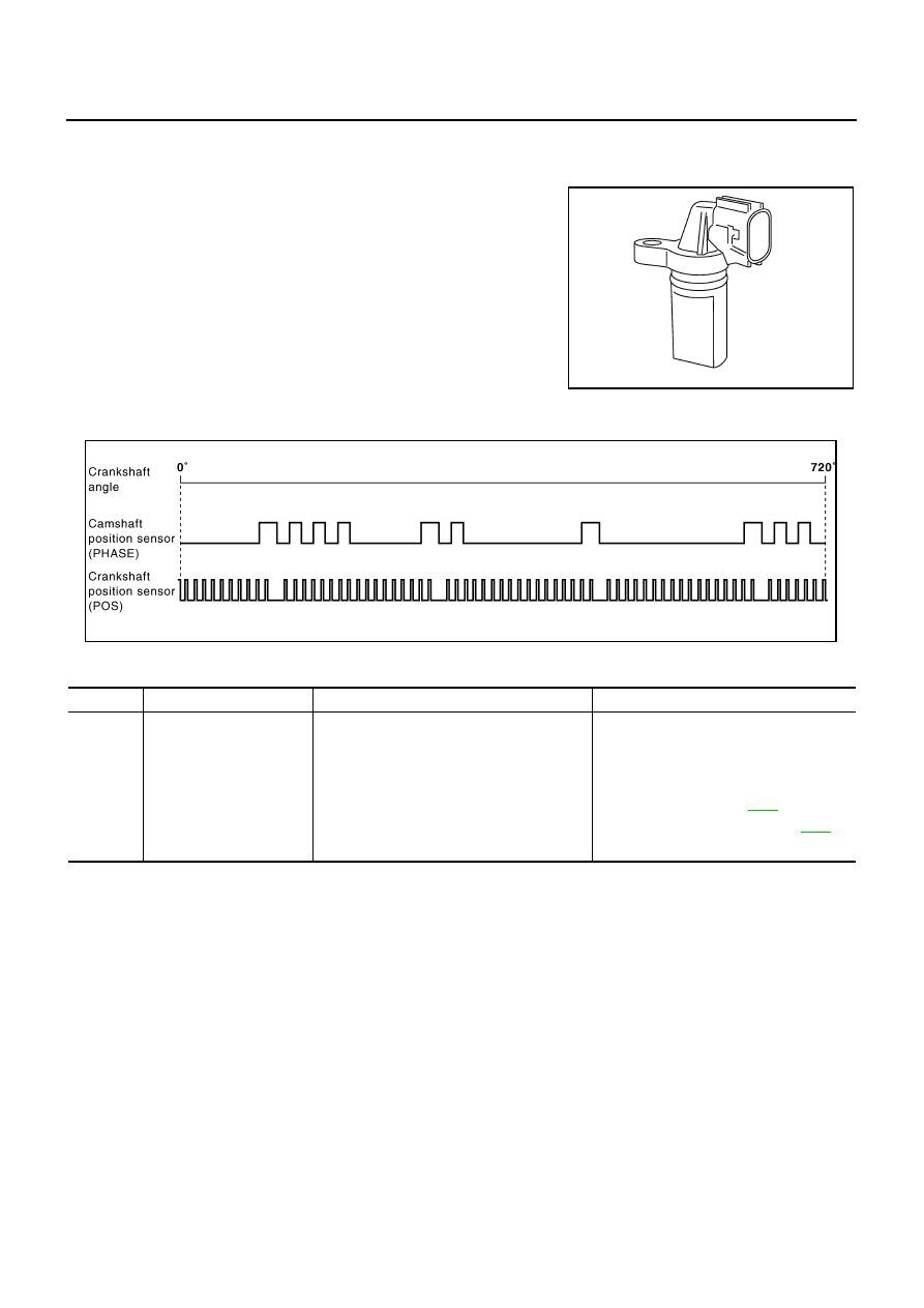
Component Description
NBS005GL
The camshaft position sensor (PHASE) senses the protrusion of
exhaust valve cam sprocket to identify a particular cylinder. The
camshaft position sensor (PHASE) senses the piston position.
When the crankshaft position sensor (POS) system becomes inoper-
ative, the camshaft position sensor (PHASE) provides various con-
trols of engine parts instead, utilizing timing of cylinder identification
signals.
The sensor consists of a permanent magnet and Hall IC.
When engine is running, the high and low parts of the teeth cause
the gap with the sensor to change.
The changing gap causes the magnetic field near the sensor to
change.
Due to the changing magnetic field, the voltage from the sensor changes.
ECM receives the signals as shown in the figure.
On Board Diagnosis Logic
NBS005GM
PBIB0562E
PBIB2448E
DTC No.
Trouble diagnosis name
DTC detecting condition
Possible cause
P0340
0340
Camshaft position sensor
(PHASE) circuit
●
The cylinder No. signal is not sent to ECM
for the first few seconds during engine
cranking.
●
The cylinder No. signal is not sent to ECM
during engine running.
●
The cylinder No. signal is not in the normal
pattern during engine running.
●
Harness or connectors
(The sensor circuit is open or shorted)
●
Camshaft position sensor (PHASE)
●
Camshaft sprocket (EXH)
●
●
Starting system circuit (Refer to
●
Dead (Weak) battery
DTC P0340 CAMSHAFT POSITION (CMP) SENSOR (PHASE)
EC-1083
[VK45DE]
C
D
E
F
G
H
I
J
K
L
M
A
EC
DTC Confirmation Procedure
NBS005GN
NOTE:
If DTC Confirmation Procedure has been previously conducted, always turn ignition switch OFF and wait at
least 10 seconds before conducting the next test.
TESTING CONDITION:
Before performing the following procedure, confirm that battery voltage is more than 10.5V with igni-
tion switch ON.
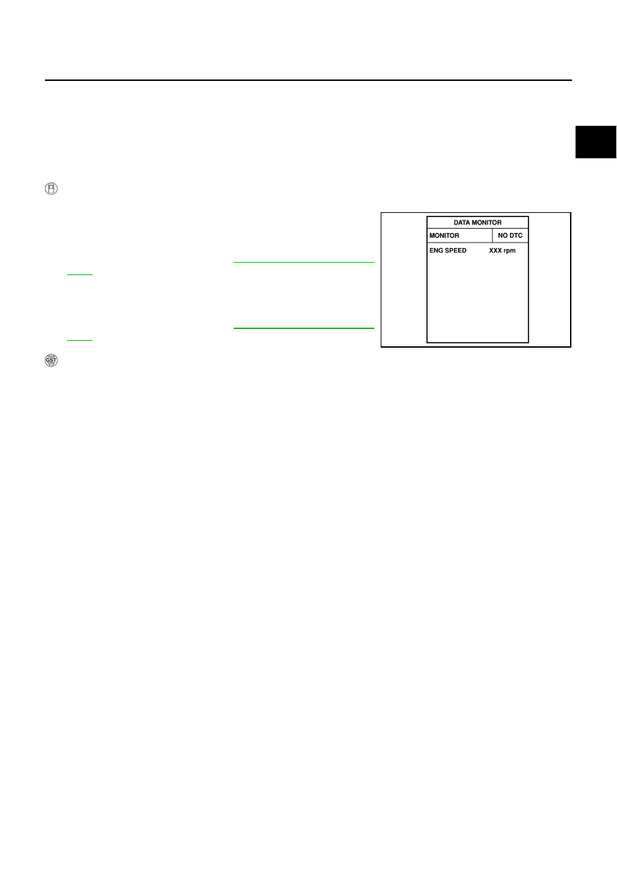
WITH CONSULT-II
1.
Turn ignition switch ON.
2.
Select “DATA MONITOR” mode with CONSULT-II.
3.
Crank engine for at least 2 seconds and run it for at least 5 sec-
onds at idle speed.
4.
If 1st trip DTC is detected, go to
.
If 1st trip DTC is not detected, go to next step.
5.
Maintaining engine speed at more than 800 rpm for at least 5
seconds.
6.
If 1st trip DTC is detected, go to
.
WITH GST
Follow the procedure “WITH CONSULT-II” above.
SEF058Y
EC-1084
[VK45DE]
DTC P0340 CAMSHAFT POSITION (CMP) SENSOR (PHASE)
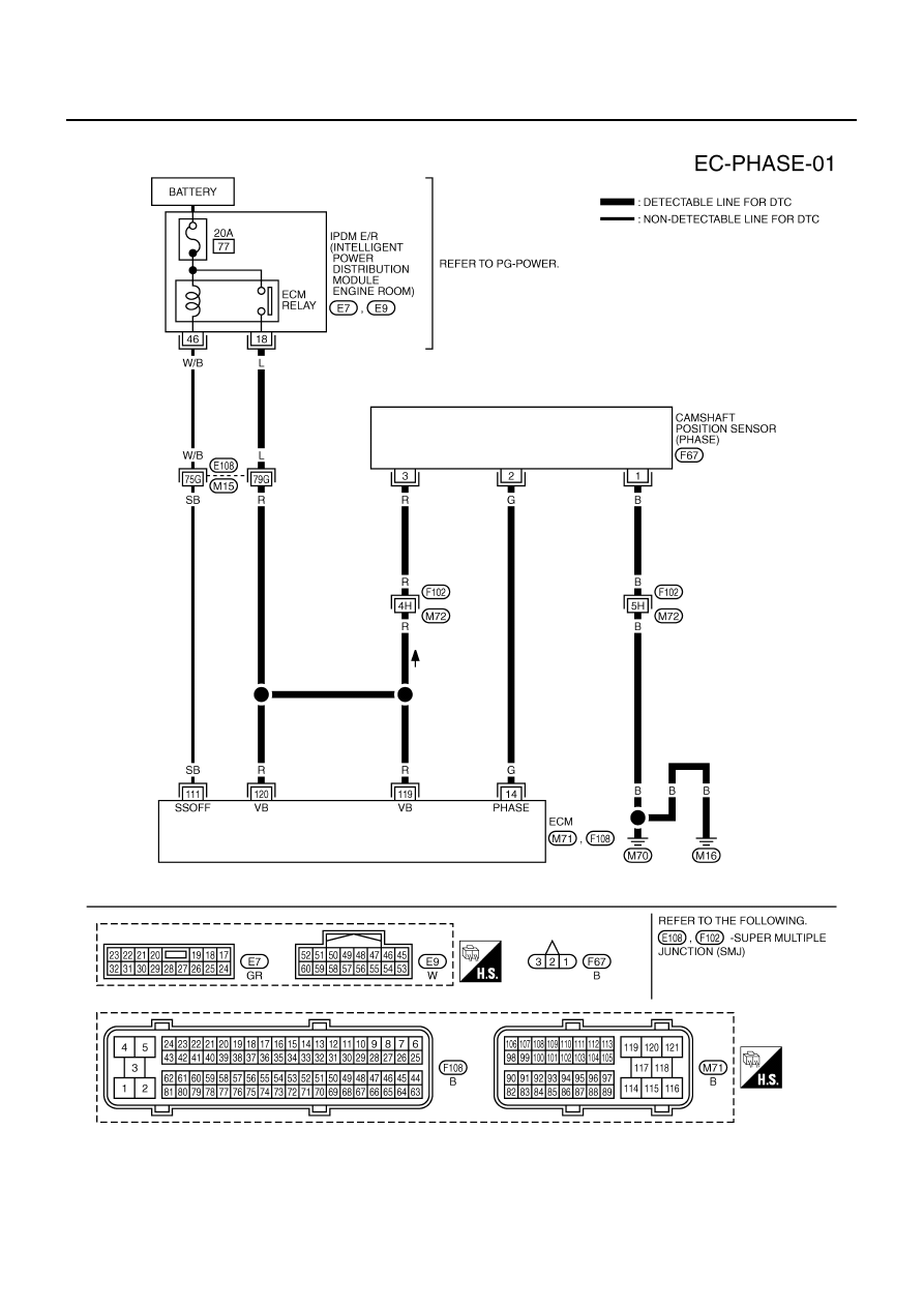
Wiring Diagram
NBS005GO
TBWT1028E
Нет комментариевНе стесняйтесь поделиться с нами вашим ценным мнением.
Текст