Infiniti M35/M45 Y50. Manual — part 653
DTC P0340 CAMSHAFT POSITION (CMP) SENSOR (PHASE)
EC-1085
[VK45DE]
C
D
E
F
G
H
I
J
K
L
M
A
EC
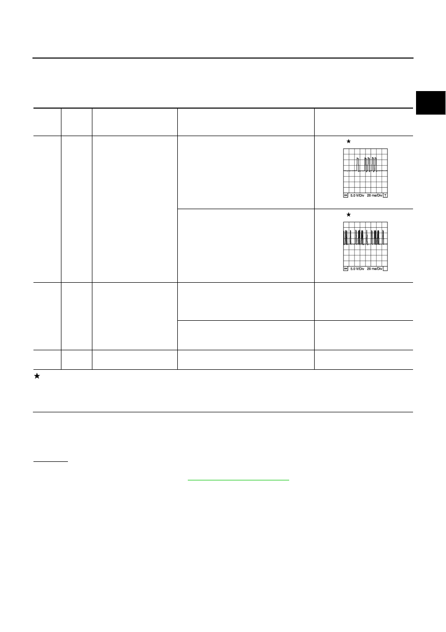
Specification data are reference values and are measured between each terminal and ground.
Pulse signal is measured by CONSULT-II.
CAUTION:
Do not use ECM ground terminals when measuring input/output voltage. Doing so may result in dam-
age to the ECM's transistor. Use a ground other than ECM terminals, such as the ground.
: Average voltage for pulse signal (Actual pulse signal can be confirmed by oscilloscope.)
Diagnostic Procedure
NBS005GP
1.
CHECK STARTING SYSTEM
Turn ignition switch to START position.
Yes or No
Yes
>> GO TO 2.
No
>> Check starting system. (Refer to
TER-
MINAL
NO.
WIRE
COLOR
ITEM
CONDITION
DATA (DC Voltage)
14
G
Camshaft position sensor
(PHASE)
[Engine is running]
●
Warm-up condition
●
Idle speed
NOTE:
The pulse cycle changes depending on rpm
at idle
1.0 - 4.0V
[Engine is running]
●
Engine speed: 2,000 rpm
1.0 - 4.0V
111
SB
ECM relay
(Self shut-off)
[Engine is running]
[Ignition switch: OFF]
●
For a few seconds after turning ignition
switch OFF
0 - 1.5V
[Ignition switch: OFF]
●
More than a few seconds after turning igni-
tion switch OFF
BATTERY VOLTAGE
(11 - 14V)
119
120
R
R
Power supply for ECM
[Ignition switch: ON]
BATTERY VOLTAGE
(11 - 14V)
PBIB1039E
PBIB1040E
Does the engine turn over?
Does the starter motor operate?
EC-1086
[VK45DE]
DTC P0340 CAMSHAFT POSITION (CMP) SENSOR (PHASE)
2.
CHECK GROUND CONNECTIONS
1.
Turn ignition switch OFF.
2.
Loosen and retighten ground screws on the body.
Refer to
OK or NG
OK
>> GO TO 3.
NG
>> Repair or replace ground connections.
3.
CHECK CAMSHAFT POSITION (CMP) SENSOR (PHASE) POWER SUPPLY CIRCUIT
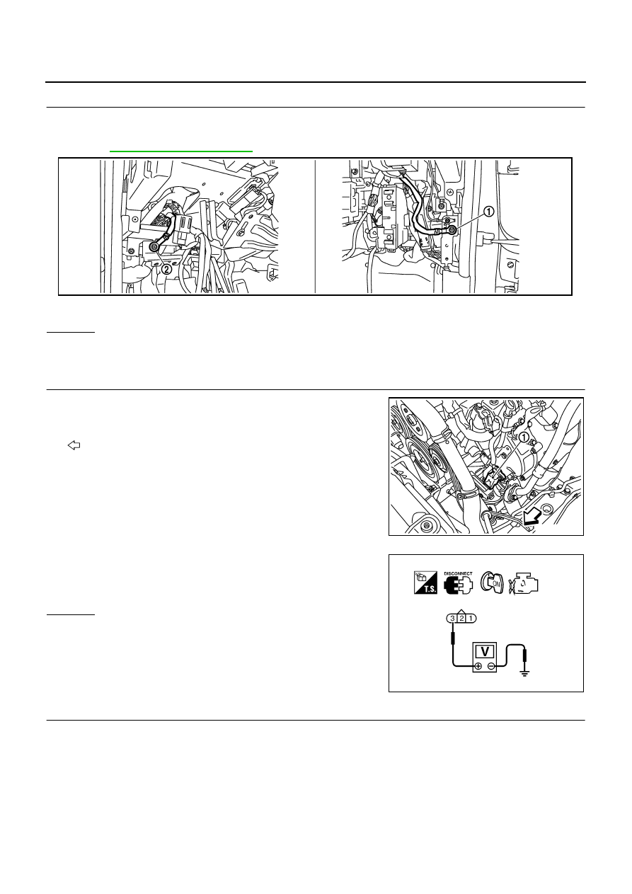
1.
Disconnect camshaft position (CMP) sensor (PHASE) (1) har-
ness connector.
–
Illustration shows the view with intake air duct removed.
–
: Vehicle front
2.
Turn ignition switch ON.
3.
Check voltage between CMP sensor (PHASE) terminal 3 and
ground with CONSULT-II or tester.
OK or NG
OK
>> GO TO 5.
NG
>> GO TO 4.
4.
DETECT MALFUNCTIONING PART
Check the following.
●
Harness connectors E108, M15
●
Harness connectors F102, M72
●
Harness for open or short between camshaft position sensor (PHASE) and ECM
●
Harness for open or short between camshaft position sensor (PHASE) and IPDM E/R
>> Repair open circuit or short to ground or short to power in harness or connectors.
1.
Body ground M70
2.
Body ground M16
PBIB2782E
PBIB2683E
Voltage: Battery voltage
SEF481Y

DTC P0340 CAMSHAFT POSITION (CMP) SENSOR (PHASE)
EC-1087
[VK45DE]
C
D
E
F
G
H
I
J
K
L
M
A
EC
5.
CHECK CMP SENSOR (PHASE) GROUND CIRCUIT FOR OPEN AND SHORT
1.
Turn ignition switch OFF.
2.
Check harness continuity between CMP sensor (PHASE) terminal 1 and ground.
Refer to Wiring Diagram.
3.
Also check harness for short to power.
OK or NG
OK
>> GO TO 7.
NG
>> GO TO 6.
6.
DETECT MALFUNCTIONING PART
Check the following.
●
Harness connectors F102, M72
●
Harness for open or short between CMP sensor (PHASE) and ground
>> Repair open circuit or short to power in harness or connectors.
7.
CHECK CMP SENSOR (PHASE) INPUT SIGNAL CIRCUIT FOR OPEN AND SHORT
1.
Disconnect ECM harness connector.
2.
Check harness continuity between ECM terminal 14 and CMP sensor (PHASE) terminal 2.
Refer to Wiring Diagram.
3.
Also check harness for short to ground and short to power.
OK or NG
OK
>> GO TO 8.
NG
>> Repair open circuit or short to ground or short to power in harness or connectors.
8.
CHECK CAMSHAFT POSITION SENSOR (PHASE)
Refer to
EC-1088, "Component Inspection"
.
OK or NG
OK
>> GO TO 9.
NG
>> Replace camshaft position sensor (PHASE).
9.
CHECK CAMSHAFT SPROCKET (EXH)
Visually check camshaft sprocket (EXH) for chipping.
OK or NG
OK
>> GO TO 10.
NG
>> Replace camshaft sprocket (exhaust).
10.
CHECK INTERMITTENT INCIDENT
Refer to
EC-857, "TROUBLE DIAGNOSIS FOR INTERMITTENT INCIDENT"
>> INSPECTION END
Continuity should exist.
Continuity should exist.
EC-1088
[VK45DE]
DTC P0340 CAMSHAFT POSITION (CMP) SENSOR (PHASE)
Component Inspection
NBS005GQ
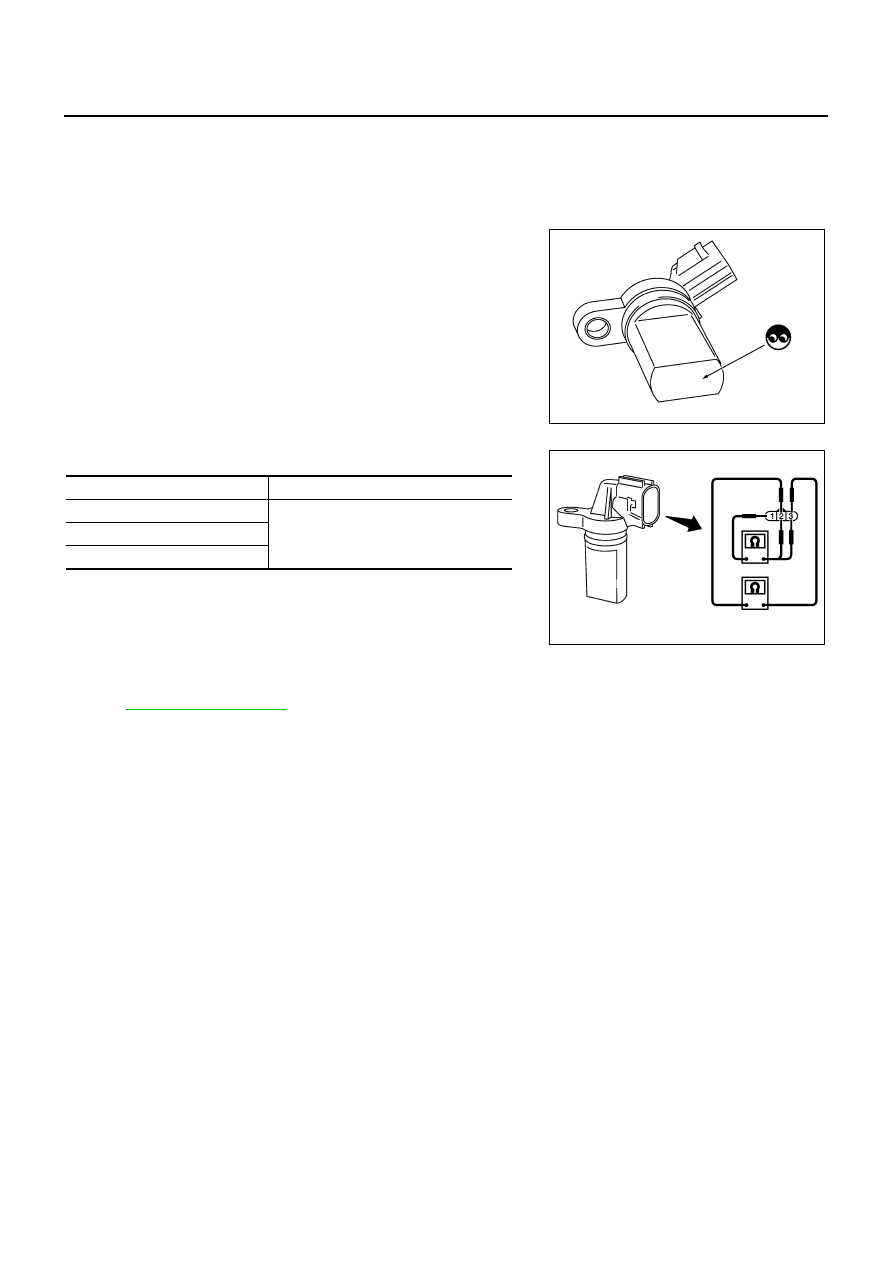
CAMSHAFT POSITION SENSOR (PHASE)
1.
Loosen the fixing bolt of the sensor.
2.
Disconnect camshaft position sensor (PHASE) harness connector.
3.
Remove the sensor.
4.
Visually check the sensor for chipping.
5.
Check resistance as shown in the figure.
Removal and Installation
NBS005GR
CAMSHAFT POSITION SENSOR (PHASE)
Refer to
PBIB0563E
Terminal No. (Polarity)
Resistance
Ω
[at 25
°
C (77
°
F)]
3(+) - 1 (-)
Except 0 or
∞
2 (+) - 1 (-)
3 (+) - 2 (-)
PBIB0564E
Нет комментариевНе стесняйтесь поделиться с нами вашим ценным мнением.
Текст