Infiniti M35/M45 Y50. Manual — part 650
DTC P0327, P0328, P0332, P0333 KS
EC-1073
[VK45DE]
C
D
E
F
G
H
I
J
K
L
M
A
EC
5.
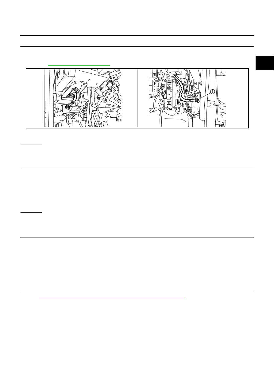
CHECK GROUND CONNECTIONS
1.
Turn ignition switch OFF.
2.
Loosen and retighten ground screws on the body.
Refer to
OK or NG
OK
>> GO TO 6.
NG
>> Repair or replace ground connections.
6.
CHECK KNOCK SENSOR SHIELD CIRCUIT FOR OPEN AND SHORT
1.
Disconnect knock sensor harness connector.
2.
Check harness continuity between knock sensor terminal 2 and ground.
Refer to Wiring Diagram.
3.
Also check harness for short to power.
OK or NG
OK
>> GO TO 8.
NG
>> GO TO 7.
7.
DETECT MALFUNCTIONING PART
Check the following.
●
Harness connectors F47, F241
●
Harness connectors F102, M72
●
Harness for open or short between knock sensor terminal 2 and ground
>> Repair open circuit or short to power in harness or connectors.
8.
CHECK INTERMITTENT INCIDENT
Refer to
EC-857, "TROUBLE DIAGNOSIS FOR INTERMITTENT INCIDENT"
>> INSPECTION END
1.
Body ground M70
2.
Body ground M16
PBIB2782E
Continuity should exist.
EC-1074
[VK45DE]
DTC P0327, P0328, P0332, P0333 KS
Component Inspection
NBS005GB
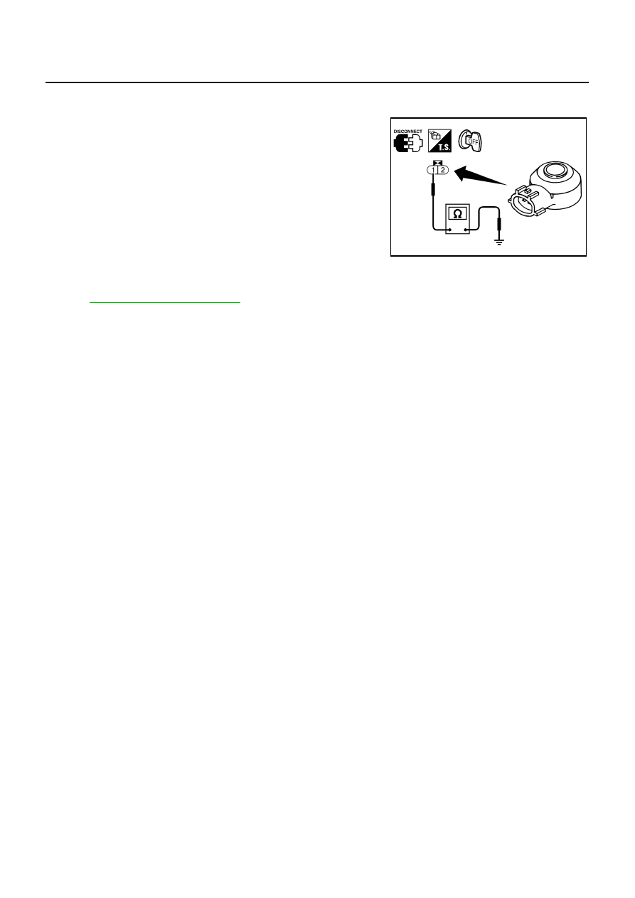
KNOCK SENSOR
Check resistance between knock sensor terminal 1 and ground.
NOTE:
It is necessary to use an ohmmeter which can measure more
than 10 M
Ω
.
CAUTION:
Do not use any knock sensors that have been dropped or phys-
ically damaged. Use only new ones.
Removal and Installation
NBS005GC
KNOCK SENSOR
Refer to
Resistance: Approximately 532 - 588 k
Ω
[at 20
°
C (68
°
F)]
SEF111Y
DTC P0335 CKP SENSOR (POS)
EC-1075
[VK45DE]
C
D
E
F
G
H
I
J
K
L
M
A
EC
DTC P0335 CKP SENSOR (POS)
PFP:23731
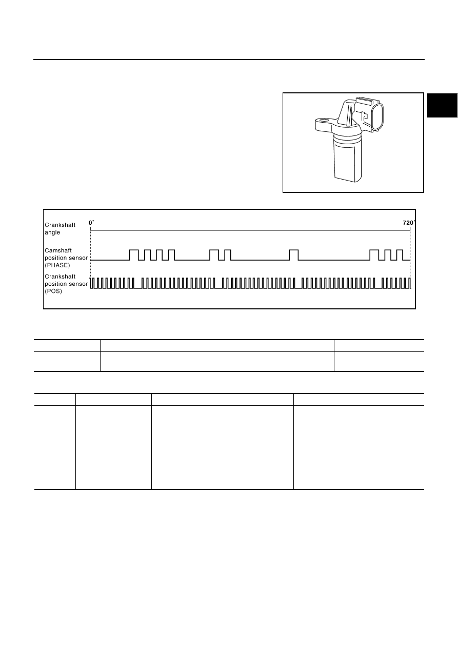
Component Description
NBS005GD
The crankshaft position sensor (POS) is located on the A/T con-
verter housing facing the gear teeth (cogs) of the signal plate. It
detects the fluctuation of the engine revolution.
The sensor consists of a permanent magnet and Hall IC.
When the engine is running, the high and low parts of the teeth
cause the gap with the sensor to change.
The changing gap causes the magnetic field near the sensor to
change.
Due to the changing magnetic field, the voltage from the sensor
changes.
The ECM receives the voltage signal and detects the fluctuation of
the engine revolution.
ECM receives the signals as shown in the figure.
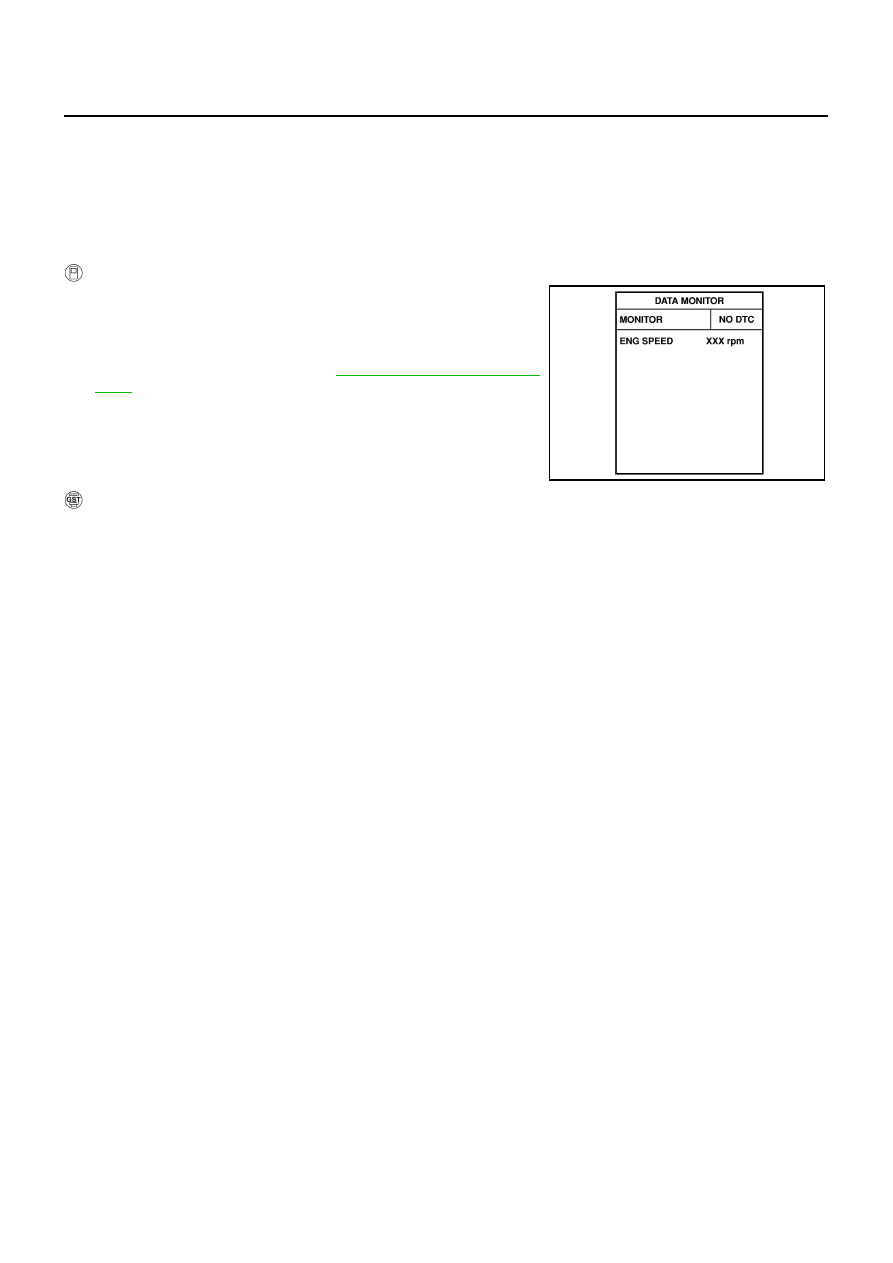
CONSULT-II Reference Value in Data Monitor Mode
NBS005GE
Specification data are reference values.
On Board Diagnosis Logic
NBS005GF
PBIB0562E
PBIB2448E
MONITOR ITEM
CONDITION
SPECIFICATION
ENG SPEED
●
Run engine and compare CONSULT-II value with the tachometer indication.
Almost the same speed as
the tachometer indication.
DTC No.
Trouble diagnosis name
DTC detecting condition
Possible cause
P0335
0335
Crankshaft position
sensor (POS) circuit
●
The crankshaft position sensor (POS) signal
is not detected by the ECM during the first
few seconds of engine cranking.
●
The proper pulse signal from the crankshaft
position sensor (POS) is not sent to ECM
while the engine is running.
●
The crankshaft position sensor (POS) signal
is not in the normal pattern during engine
running.
●
Harness or connectors
(The sensor circuit is open or shorted)
●
Crankshaft position sensor (POS)
●
Signal plate
EC-1076
[VK45DE]
DTC P0335 CKP SENSOR (POS)
DTC Confirmation Procedure
NBS005GG
NOTE:
If DTC Confirmation Procedure has been previously conducted, always turn ignition switch OFF and wait at
least 10 seconds before conducting the next test.
TESTING CONDITION:
Before performing the following procedure, confirm that battery voltage is more than 10.5V with igni-
tion switch ON.
WITH CONSULT-II
1.
Turn ignition switch ON and select “DATA MONITOR” mode with
CONSULT-II.
2.
Crank engine for at least 2 seconds and run it for at least 5 sec-
onds at idle speed.
3.
If 1st trip DTC is detected, go to
.
WITH GST
Follow the procedure “WITH CONSULT-II” above.
SEF058Y
Нет комментариевНе стесняйтесь поделиться с нами вашим ценным мнением.
Текст