Infiniti M35/M45 Y50. Manual — part 776
FSU-1
FRONT SUSPENSION
E SUSPENSION
CONTENTS
C
D
F
G
H
I
J
K
L
M
SECTION
FSU
A
B
FSU
FRONT SUSPENSION
2WD
PRECAUTIONS . . . . . . . . . . . . . . .. 3
Caution . . . . . . . . . . . . . . . . . . 3
PREPARATION . . . . . . . . . . . . . . ... 4
Special Service Tools [SST] . . . . . . . . . . 4
Commercial Service Tools . . . . . . . . . . 4
NOISE, VIBRATION AND HARSHNESS (NVH)
TROUBLESHOOTING . . . . . . . . . . . . 5
NVH Troubleshooting Chart . . . . . . . . . . 5
FRONT SUSPENSION ASSEMBLY . . . . . . ... 6
On-Vehicle Inspection . . . . . . . . . . . .. 6
Wheel Alignment Inspection . . . . . . . . . . 6
Components . . . . . . . . . . . . . . . . 8
Removal and Installation . . . . . . . . . . .. 9
REMOVAL . . . . . . . . . . . . . . . . 9
INSTALLATION . . . . . . . . . . . . ... 10
COIL SPRING AND SHOCK ABSORBER . . . . 11
Removal and Installation . . . . . . . . . . .11
REMOVAL . . . . . . . . . . . . . . . 11
INSTALLATION . . . . . . . . . . . . . 11
Disassembly and Assembly . . . . . . . . . 11
TRANSVERSE LINK . . . . . . . . . . . . 14
Removal and Installation . . . . . . . . . . 14
UPPER LINK . . . . . . . . . . . . . . . . 16
Removal and Installation . . . . . . . . . . 16
STABILIZER BAR . . . . . . . . . . . . . . 18
Removal and Installation . . . . . . . . . . 18
SERVICE DATA AND SPECIFICATIONS (SDS) . .. 19
AWD
PRECAUTIONS . . . . . . . . . . . . . . 21
Caution . . . . . . . . . . . . . . . . ... 21
PREPARATION . . . . . . . . . . . . . . . 22
Special Service Tools [SST] . . . . . . . . ... 22
Commercial Service Tools . . . . . . . . . .. 22
NOISE, VIBRATION AND HARSHNESS (NVH)
TROUBLESHOOTING . . . . . . . . . . . .. 23
NVH Troubleshooting Chart . . . . . . . . ... 23
FRONT SUSPENSION ASSEMBLY . . . . . . . 24
On-Vehicle Inspection . . . . . . . . . . . . 24
FSU-2
Components . . . . . . . . . . . . . . ... 26
Removal and Installation . . . . . . . . . . 27
REMOVAL . . . . . . . . . . . . . . ... 27
INSTALLATION . . . . . . . . . . . . . 28
COIL SPRING AND SHOCK ABSORBER . . . ... 29
Removal and Installation . . . . . . . . . . 29
REMOVAL . . . . . . . . . . . . . . ... 29
INSTALLATION . . . . . . . . . . . . . 29
Disassembly and Assembly . . . . . . . . . 29
TRANSVERSE LINK . . . . . . . . . . . . . 32
Removal and Installation . . . . . . . . . . 32
UPPER LINK . . . . . . . . . . . . . . . .34
Removal and Installation . . . . . . . . . . .34
STABILIZER BAR . . . . . . . . . . . . . .36
Removal and Installation . . . . . . . . . . .36
PRECAUTIONS
FSU-3
[2WD]
C
D
F
G
H
I
J
K
L
M
A
B
FSU
[2WD]
PRECAUTIONS
PFP:00001
Caution
NES000I6
●
When installing rubber bushings, the final tightening must be carried out under unladen conditions with
tires on ground. Oil might shorten the life of rubber bushings. Be sure to wipe off any spilled oil.
–
Unladen conditions mean that fuel, engine coolant and lubricant are full. Spare tire, jack, hand tools and
mats are in designated positions.
●
After servicing suspension parts, be sure to check wheel alignment.
●
Self-lock nuts are not reusable. Always use new ones when installing. Since new self-lock nuts are pre-
oiled, tighten as they are.
FSU-4
[2WD]
PREPARATION
PREPARATION
PFP:00002
Special Service Tools [SST]
NES000I7
The actual shapes of Kent-Moore tools may differ from those of special service tools illustrated here.
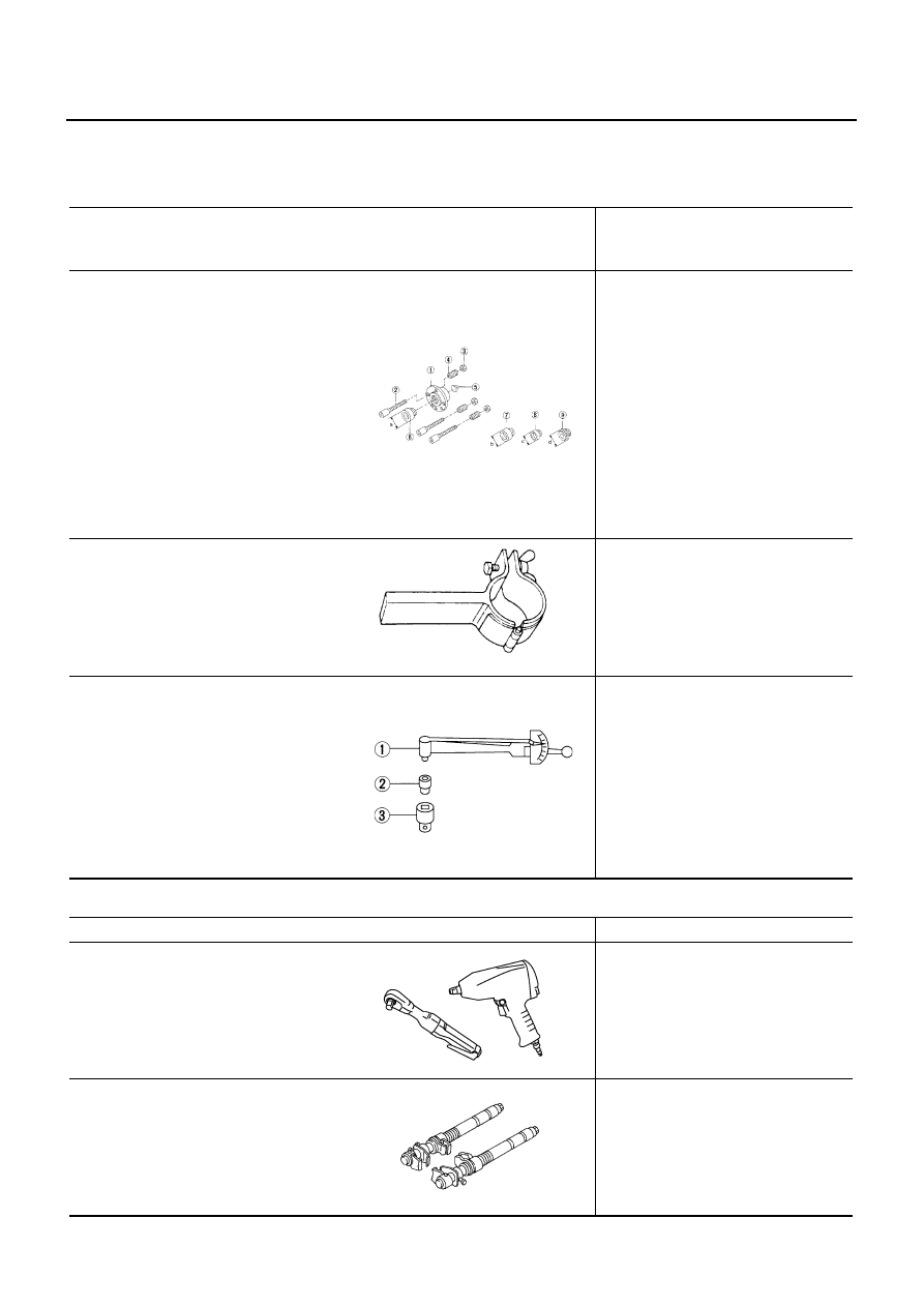
Commercial Service Tools
NES000I8
Tool number
(Kent-Moore No.)
Tool name
Description
KV991040S0
(
—
)
CCK gauge attachment
1. Plate
2. Guide bolt
3. Nut
4. Spring
5. Center plate
6. KV99104020 Adapter A
a: 72 mm (2.83 in) dia.
7. KV99104030 Adapter B
b: 65 mm (2.56 in) dia.
8. KV99104040 Adapter C
c: 57 mm (2.24 in) dia.
9. KV99104050 Adapter D
d: 53.4 mm (2.102 in) dia.
Measuring wheel alignment
ST35652000
(
—
)
Strut attachment
Disassembling and assembling shock
absorber
ST3127S000
(See J-25765-A)
Preload Gauge
1. GG91030000
(J-25765-A)
Torque wrench
2. HT62940000
(
—
)
Socket adapter
3. HT62900000
(
—
)
Socket adapter
Measuring rotating torque of ball joint
S-NT498
ZZA0807D
NT124
Tool name
Description
Power tool
●
Removing wheel nuts
●
Removing torque member fixing bolts
●
Removing undercover
●
Removing front suspension compo-
nents parts
●
Removing hub lock nut
Spring compressor
Removing and installing coil spring
PBIC0190E
S-NT717
Нет комментариевНе стесняйтесь поделиться с нами вашим ценным мнением.
Текст