Infiniti M35/M45 Y50. Manual — part 528

DTC P1574 ICC VEHICLE SPEED SENSOR
EC-585
[VQ35DE]
C
D
E
F
G
H
I
J
K
L
M
A
EC
Diagnostic Procedure
NBS0055H
1.
CHECK DTC WITH TCM
Check DTC with TCM. Refer to
AT-40, "ON BOARD DIAGNOSTIC (OBD) SYSTEM"
OK or NG
OK
>> GO TO 2.
NG
>> Perform trouble shooting relevant to DTC indicated.
2.
CHECK DTC WITH “ABS ACTUATOR AND ELECTRIC UNIT (CONTROL UNIT)”
Refer to
.
OK or NG
OK
>> GO TO 3.
NG
>> Repair or replace.
3.
CHECK DTC WITH “UNIFIED METER AND A/C AMP.”
Check combination meter function.
Refer to
DI-28, "UNIFIED METER AND A/C AMP"
.
>> INSPECTION END
EC-586
[VQ35DE]
DTC P1574 ASCD VEHICLE SPEED SENSOR
DTC P1574 ASCD VEHICLE SPEED SENSOR
PFP:31036
Component Description
NBS0055I
The ECM receives two vehicle speed sensor signals via CAN communication line. One is sent from “unified
meter and A/C amp.”, and the other is from TCM (Transmission control module). The ECM uses these signals
for ASCD control. Refer to
EC-36, "AUTOMATIC SPEED CONTROL DEVICE (ASCD)"
for ASCD functions.
On Board Diagnosis Logic
NBS0055J
This self-diagnosis has the one trip detection logic.
The MIL will not light up for this diagnosis.
NOTE:
●
If DTC P1574 is displayed with DTC U1000, U1001, first perform the trouble diagnosis for DTC
U1000, U1001. Refer to
EC-161, "DTC U1000, U1001 CAN COMMUNICATION LINE"
.
●
If DTC P1574 is displayed with DTC U1010, first perform the trouble diagnosis for DTC U1010.
Refer to
EC-164, "DTC U1010 CAN COMMUNICATION"
.
●
If DTC P1574 is displayed with DTC P0500, first perform the trouble diagnosis for DTC P0500.
Refer to
●
If DTC P1574 is displayed with DTC P0605, first perform the trouble diagnosis for DTC P0605.
Refer to
DTC Confirmation Procedure
NBS0055K
CAUTION:
Always drive vehicle at a safe speed.
NOTE:
If DTC Confirmation Procedure has been previously conducted, always turn ignition switch OFF and wait at
least 10 seconds before conducting the next test.
TESTING CONDITION:
Step 3 may be conducted with the drive wheels lifted in the shop or by driving the vehicle. If a road test
is expected to be easier, it is unnecessary to lift the vehicle.
WITH CONSULT-II
1.
Start engine (VDC switch OFF).
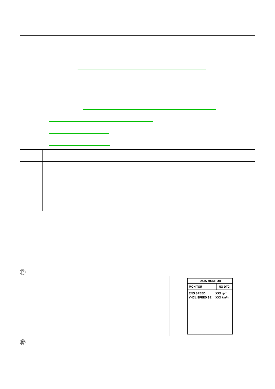
2.
Select “DATA MONITOR” mode with CONSULT-II.
3.
Drive the vehicle at more than 40 km/h (25 MPH).
4.
If DTC is detected, go to
EC-587, "Diagnostic Procedure"
.
WITH GST
Follow the procedure “WITH CONSULT-II” above.
DTC No.
Trouble diagnosis
name
DTC detecting condition
Possible cause
P1574
1574
ASCD vehicle speed
sensor
ECM detects a difference between two vehicle
speed signals is out of the specified range.
●
Harness or connectors
(The CAN communication line is open or
shorted.)
●
Unified meter and A/C amp.
●
ABS actuator and electric unit (control unit)
●
Wheel sensor
●
TCM
●
ECM
PBIB2673E

DTC P1574 ASCD VEHICLE SPEED SENSOR
EC-587
[VQ35DE]
C
D
E
F
G
H
I
J
K
L
M
A
EC
Diagnostic Procedure
NBS0055L
1.
CHECK DTC WITH TCM
Check DTC with TCM. Refer to
AT-40, "ON BOARD DIAGNOSTIC (OBD) SYSTEM"
OK or NG
OK
>> GO TO 2.
NG
>> Perform trouble shooting relevant to DTC indicated.
2.
CHECK DTC WITH “ABS ACTUATOR AND ELECTRIC UNIT (CONTROL UNIT)”
Refer to
.
OK or NG
OK
>> GO TO 3.
NG
>> Repair or replace.
3.
CHECK DTC WITH “UNIFIED METER AND A/C AMP.”
Refer to
DI-28, "UNIFIED METER AND A/C AMP"
.
>> INSPECTION END

EC-588
[VQ35DE]
DTC P1715 INPUT SPEED SENSOR (TURBINE REVOLUTION SENSOR)
DTC P1715 INPUT SPEED SENSOR (TURBINE REVOLUTION SENSOR)
PFP:31935
Description
NBS0055M
ECM receives turbine revolution sensor signal from TCM through CAN communication line. ECM uses this
signal for engine control.
CONSULT-II Reference Value in Data Monitor Mode
NBS0055N
Specification data are reference values.
On Board Diagnosis Logic
NBS0055O
NOTE:
●
If DTC P1715 is displayed with DTC U1000, U1001 first perform the trouble diagnosis for DTC
U1000, U1001. Refer to
EC-161, "DTC U1000, U1001 CAN COMMUNICATION LINE"
.
●
If DTC P1715 is displayed with DTC U1010, first perform the trouble diagnosis for DTC U1010.
Refer to
EC-164, "DTC U1010 CAN COMMUNICATION"
.
●
If DTC P1715 is displayed with DTC P0605, first perform the trouble diagnosis for DTC P0605.
Refer to
●
If DTC P1715 is displayed with DTC P0335, first perform the trouble diagnosis for DTC P0335.
Refer to
EC-364, "DTC P0335 CKP SENSOR (POS)"
●
If DTC P1715 is displayed with DTC P0340, P0345 first perform the trouble diagnosis for DTC
P0340, P0345. Refer to
EC-371, "DTC P0340, P0345 CMP SENSOR (PHASE)"
The MIL will not lights up for this diagnosis.
Diagnostic Procedure
NBS0055P
1.
CHECK DTC WITH TCM
Check DTC with TCM. Refer to
AT-40, "ON BOARD DIAGNOSTIC (OBD) SYSTEM"
OK or NG
OK
>> GO TO 2.
NG
>> Perform trouble shooting relevant to DTC indicated.
2.
REPLACE TCM
Replace TCM. Refer to
.
>> INSPECTION END
MONITOR ITEM
CONDITION
SPECIFICATION
I/P PULLY SPD
●
Vehicle speed: More than 20 km/h (12MPH)
Almost the same speed as the
tachometer indication
DTC No.
Trouble diagnosis name
DTC detecting condition
Possible cause
P1715
1715
Input speed sensor
(Turbine revolution sen-
sor)
(TCM output)
Turbine revolution sensor signal is differ-
ent from the theoretical value calculated
by ECM from revolution sensor signal
and engine rpm signal.
●
Harness or connectors
(The CAN communication line is open or
shorted)
●
Harness or connectors
(Turbine revolution sensor circuit is open or
shorted)
●
TCM
Нет комментариевНе стесняйтесь поделиться с нами вашим ценным мнением.
Текст