Infiniti M35/M45 Y50. Manual — part 529
DTC P1805 BRAKE SWITCH
EC-589
[VQ35DE]
C
D
E
F
G
H
I
J
K
L
M
A
EC
DTC P1805 BRAKE SWITCH
PFP:25320
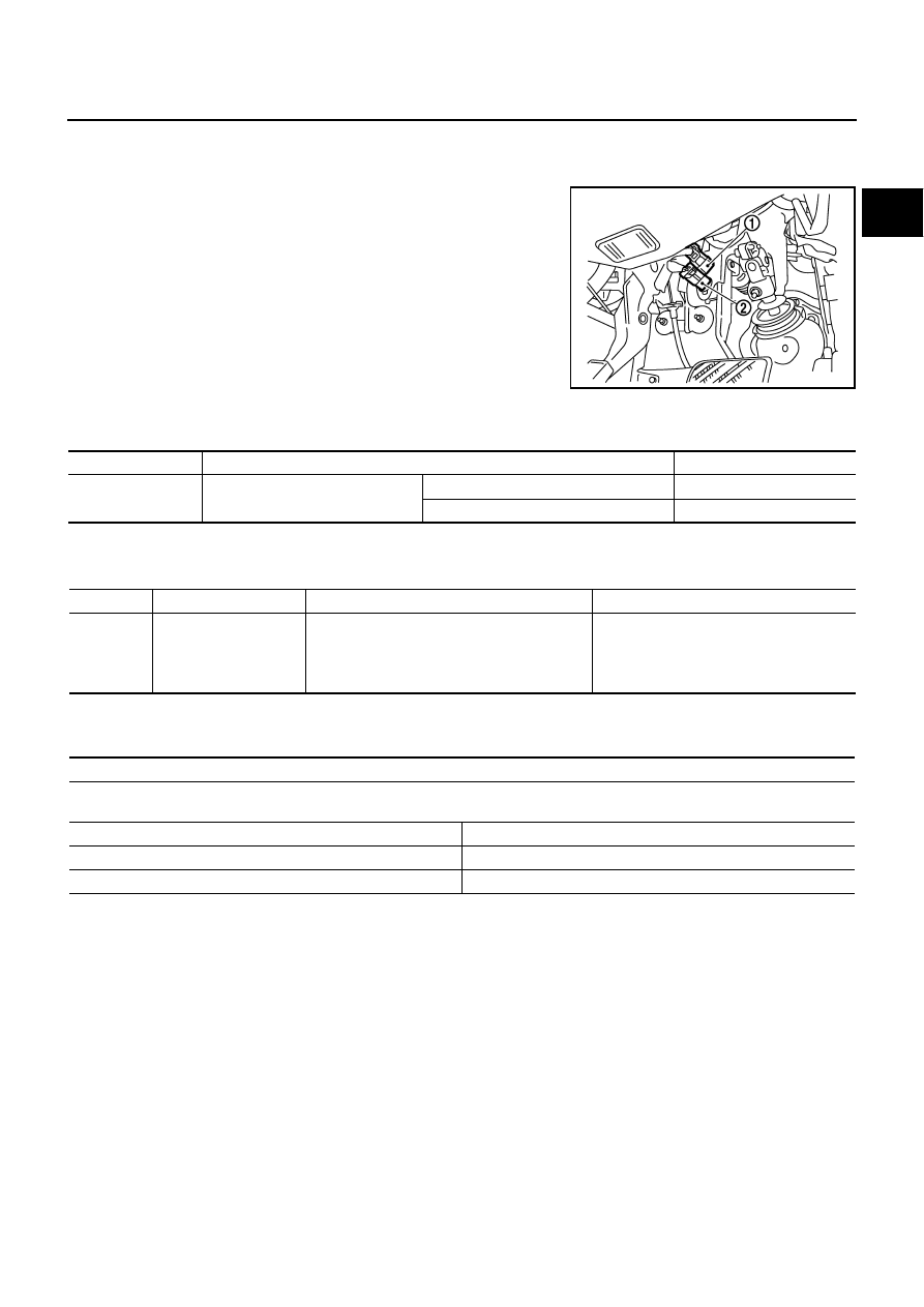
Component Description
NBS0055Q
Brake switch signal is applied to the ECM through the stop lamp
switch (1) when the brake pedal is depressed. This signal is used
mainly to decrease the engine speed when the vehicle is driving.
●
ICC brake switch (models with ICC) (2)
●
ASCD brake switch (models with ASCD) (2)
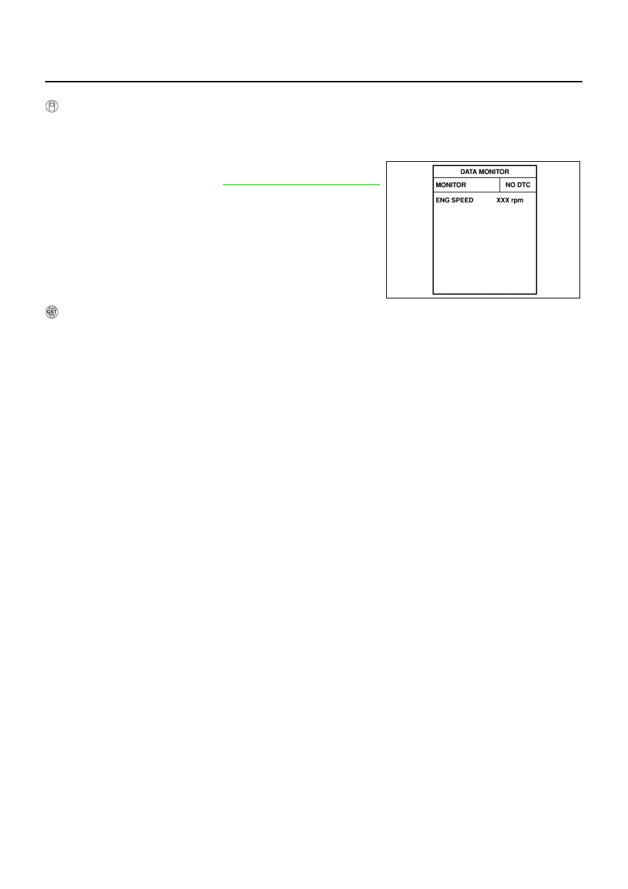
CONSULT-II Reference Value in Data Monitor Mode
NBS0055R
Specification data are reference values.
On Board Diagnosis Logic
NBS0055S
The MIL will not light up for this diagnosis.
FAIL-SAFE MODE
When the malfunction is detected, ECM enters fail-safe mode.
PBIB2705E
MONITOR ITEM
CONDITION
SPECIFICATION
BRAKE SW
●
Ignition switch: ON
Brake pedal: Fully released
OFF
Brake pedal: Slightly depressed
ON
DTC No.
Trouble diagnosis name
DTC detecting condition
Possible cause
P1805
1805
Brake switch
A brake switch signal is not sent to ECM for
extremely long time while the vehicle is driving.
●
Harness or connectors
(Stop lamp switch circuit is open or
shorted.)
●
Stop lamp switch
Engine operating condition in fail-safe mode
ECM controls the electric throttle control actuator by regulating the throttle opening to a small range.
Therefore, acceleration will be poor.
Vehicle condition
Driving condition
When engine is idling
Normal
When accelerating
Poor acceleration
EC-590
[VQ35DE]
DTC P1805 BRAKE SWITCH
DTC Confirmation Procedure
NBS0055T
WITH CONSULT-II
1.
Turn ignition switch ON.
2.
Fully depress the brake pedal for at least 5 seconds.
3.
Erase the DTC with CONSULT-II.
4.
Select “DATA MONITOR” mode with CONSULT-II.
5.
If 1st trip DTC is detected, go to
EC-592, "Diagnostic Procedure"
.
WITH GST
Follow the procedure “WITH CONSULT-II” above.
SEF058Y
DTC P1805 BRAKE SWITCH
EC-591
[VQ35DE]
C
D
E
F
G
H
I
J
K
L
M
A
EC
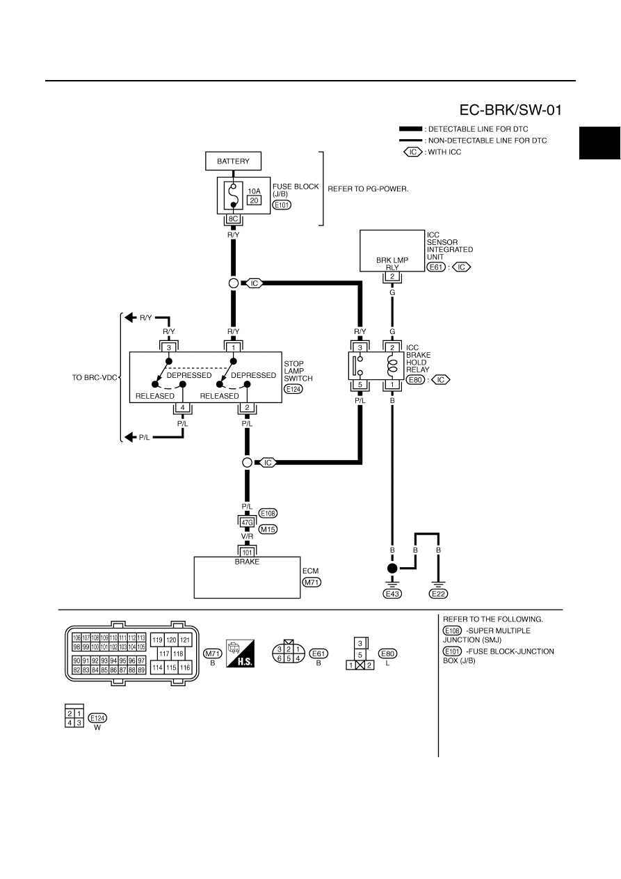
Wiring Diagram
NBS0055U
TBWT0986E

EC-592
[VQ35DE]
DTC P1805 BRAKE SWITCH
Specification data are reference values and are measured between each terminal and ground.
CAUTION:
Do not use ECM ground terminals when measuring input/output voltage. Doing so may result in dam-
age to the ECM's transistor. Use a ground other than ECM terminals, such as the ground.
Diagnostic Procedure
NBS0055V
ICC MODELS
1.
CHECK DTC WITH ICC SENSOR INTEGRATED UNIT
Refer to
ACS-40, "TROUBLE DIAGNOSIS FOR SELF-DIAGNOSTIC ITEMS"
OK or NG
OK
>> GO TO 2.
NG
>> Repair or replace.
2.
CHECK STOP LAMP SWITCH CIRCUIT
1.
Turn ignition switch OFF.
2.
Check the stop lamp when depressing and releasing the brake pedal.
OK or NG
OK
>> GO TO 5.
NG
>> GO TO 3.
TER-
MINAL
NO.
WIRE
COLOR
ITEM
CONDITION
DATA (DC Voltage)
101
V/R
Stop lamp switch
[Ignition switch: OFF]
●
Brake pedal: Fully released
Approximately 0V
[Ignition switch: OFF]
●
Brake pedal: Slightly depressed
BATTERY VOLTAGE
(11 - 14V)
Brake pedal
Stop lamp
Fully released
Not illuminated
Slightly depressed
Illuminated
Нет комментариевНе стесняйтесь поделиться с нами вашим ценным мнением.
Текст