Infiniti M35/M45 Y50. Manual — part 526

DTC P1572 ASCD BRAKE SWITCH
EC-577
[VQ35DE]
C
D
E
F
G
H
I
J
K
L
M
A
EC
DTC Confirmation Procedure
NBS0055A
CAUTION:
Always drive vehicle at a safe speed.
NOTE:
●
If DTC Confirmation Procedure has been previously conducted, always turn ignition switch OFF and wait
at least 10 seconds before conducting the next test.
●
Procedure for malfunction B is not described here. It takes extremely long time to complete procedure for
malfunction B. By performing procedure for malfunction A, the incident that causes malfunction B can be
detected.
TESTING CONDITION:
Steps 4 and 5 may be conducted with the drive wheels lifted in the shop or by driving the vehicle. If a
road test is expected to be easier, it is unnecessary to lift the vehicle.
WITH CONSULT-II
1.
Start engine (VDC switch OFF).
2.
Select “DATA MONITOR” mode with CONSULT-II.
3.
Press MAIN switch and make sure that CRUISE lamp lights up.
4.
Drive the vehicle for at least 5 consecutive seconds under the
following conditions.
If 1st trip DTC is detected, go to
EC-579, "Diagnostic Procedure"
.
If 1st trip DTC is not detected, go to the following step.
5.
Drive the vehicle for at least 5 consecutive seconds under the following conditions.
6.
If 1st trip DTC is detected, go to
EC-579, "Diagnostic Procedure"
WITH GST
Follow the procedure “WITH CONSULT-II” above.
VHCL SPEED SE
More than 30 km/h (19 MPH)
Selector lever
Suitable position
PBIB2386E
VHCL SPEED SE
More than 30 km/h (19 MPH)
Selector lever
Suitable position
Driving location
Depress the brake pedal for more than
five seconds so as not to come off from
the above-mentioned vehicle speed.
EC-578
[VQ35DE]
DTC P1572 ASCD BRAKE SWITCH
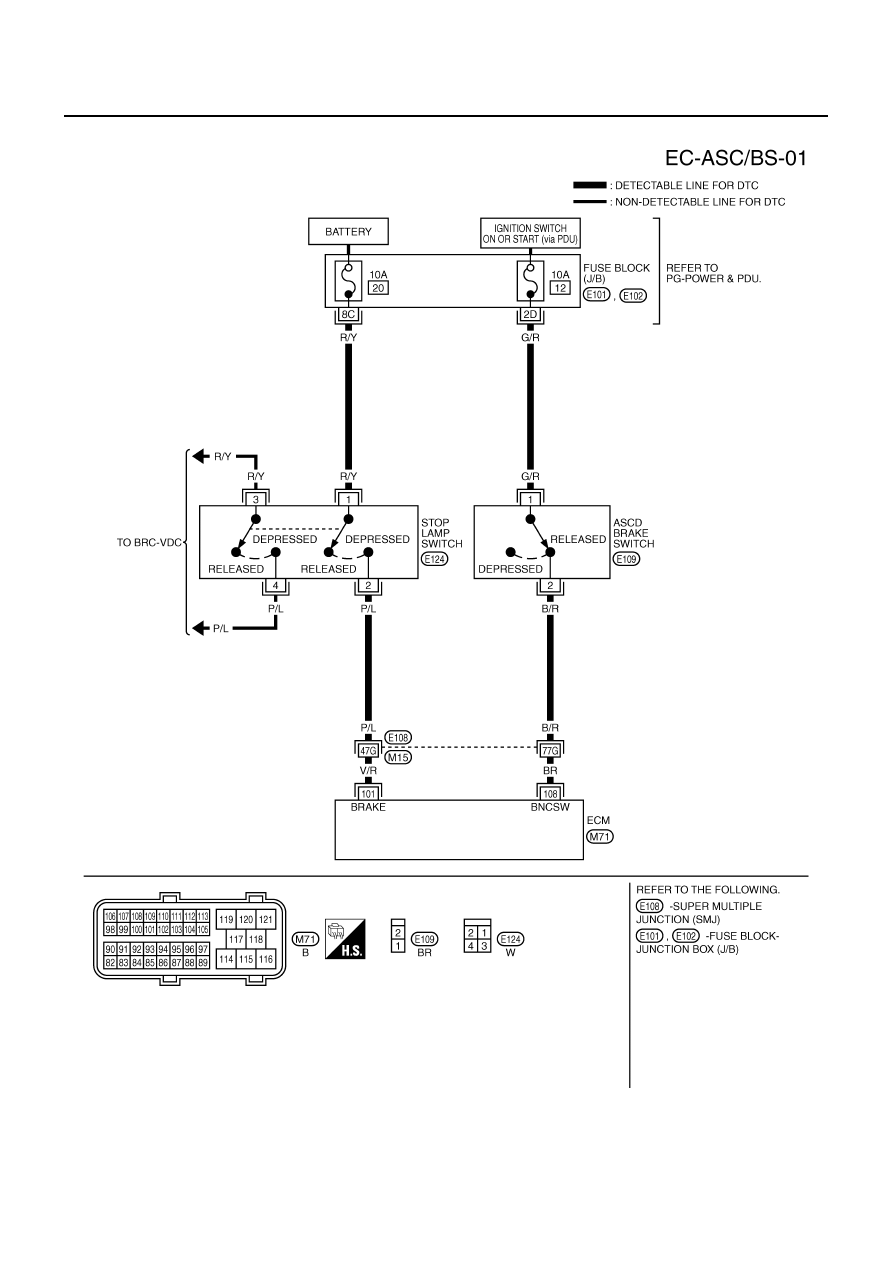
Wiring Diagram
NBS0055B
TBWT0983E

DTC P1572 ASCD BRAKE SWITCH
EC-579
[VQ35DE]
C
D
E
F
G
H
I
J
K
L
M
A
EC
Specification data are reference values and are measured between each terminal and ground.
CAUTION:
Do not use ECM ground terminals when measuring input/output voltage. Doing so may result in dam-
age to the ECM's transistor. Use a ground other than ECM terminals, such as the ground.
Diagnostic Procedure
NBS0055C
1.
CHECK OVERALL FUNCTION-I
With CONSULT-II
1.
Turn ignition switch ON.
2.
Select “BRAKE SW1” in “DATA MONITOR” mode with CONSULT-II.
3.
Check “BRAKE SW1” indication under the following conditions.
Without CONSULT-II
1.
Turn ignition switch ON.
2.
Check voltage between ECM terminal 108 and ground under the
following conditions.
OK or NG
OK
>> GO TO 2.
NG
>> GO TO 3.
TER-
MINAL
NO.
WIRE
COLOR
ITEM
CONDITION
DATA (DC Voltage)
101
V/R
Stop lamp switch
[Ignition switch: OFF]
●
Brake pedal: Fully released
Approximately 0V
[Ignition switch: OFF]
●
Brake pedal: Slightly depressed
BATTERY VOLTAGE
(11 - 14V)
108
BR
ASCD brake switch
[Ignition switch: ON]
●
Brake pedal: Slightly depressed
Approximately 0V
[Ignition switch: ON]
●
Brake pedal: Fully released
BATTERY VOLTAGE
(11 - 14V)
CONDITION
INDICATION
Brake pedal: Slightly depressed
OFF
Brake pedal: Fully released
ON
SEC011D
CONDITION
VOLTAGE
Brake pedal: Slightly depressed
Approximately 0V
Brake pedal: Fully released
Battery voltage
MBIB0061E
EC-580
[VQ35DE]
DTC P1572 ASCD BRAKE SWITCH
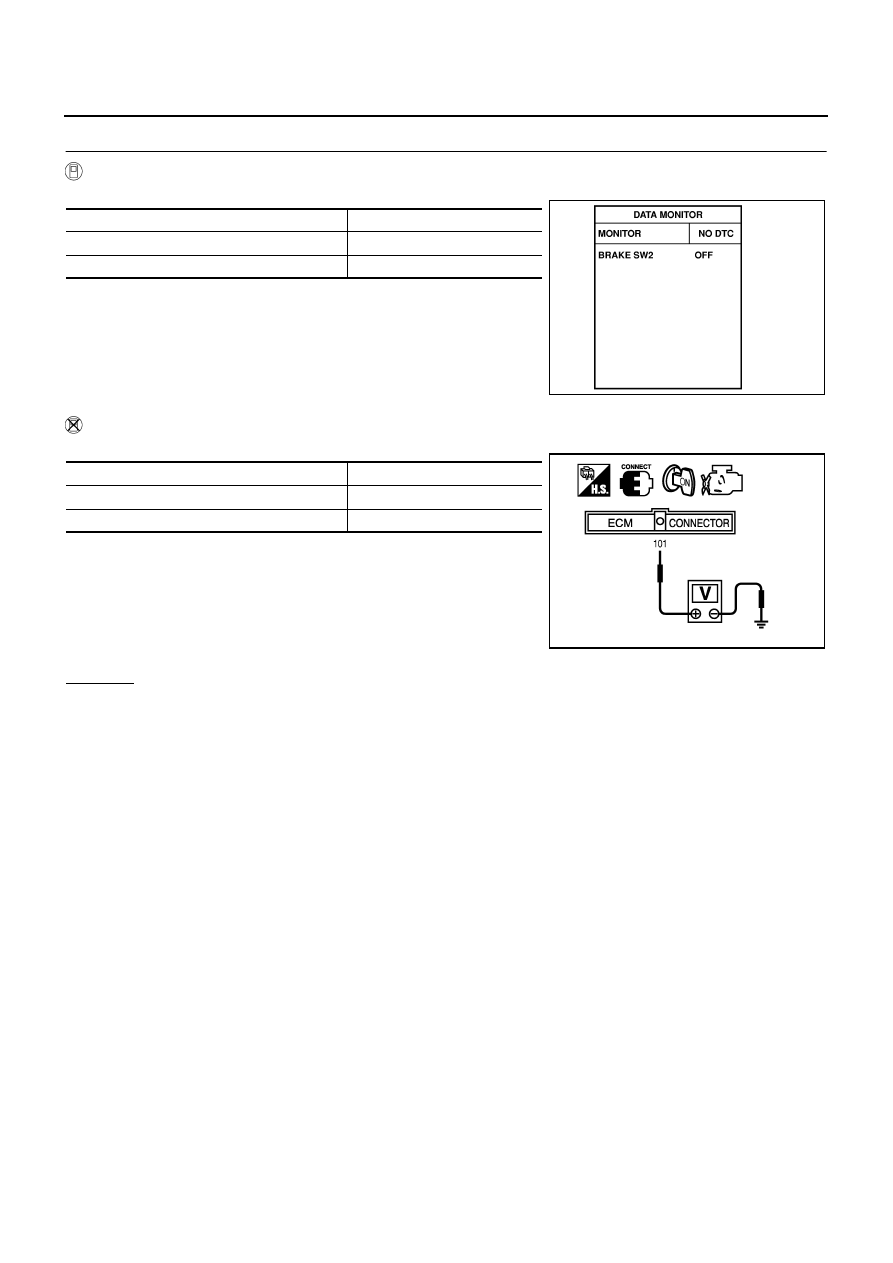
2.
CHECK OVERALL FUNCTION-II
With CONSULT-II
Check “BRAKE SW2” indication in “DATA MONITOR” mode.
Without CONSULT-II
Check voltage between ECM terminal 101 and ground under the following conditions.
OK or NG
OK
>> GO TO 13.
NG
>> GO TO 8.
CONDITION
INDICATION
Brake pedal: Fully released
OFF
Brake pedal: Slightly depressed
ON
SEC013D
CONDITION
VOLTAGE
Brake pedal: Fully released
Approximately 0V
Brake pedal: Slightly depressed
Battery voltage
PBIB1537E
Нет комментариевНе стесняйтесь поделиться с нами вашим ценным мнением.
Текст