Infiniti M35/M45 Y50. Manual — part 830
REVERSE INTERLOCK DOOR MIRROR SYSTEM
GW-117
C
D
E
F
G
H
J
K
L
M
A
B
GW
8.
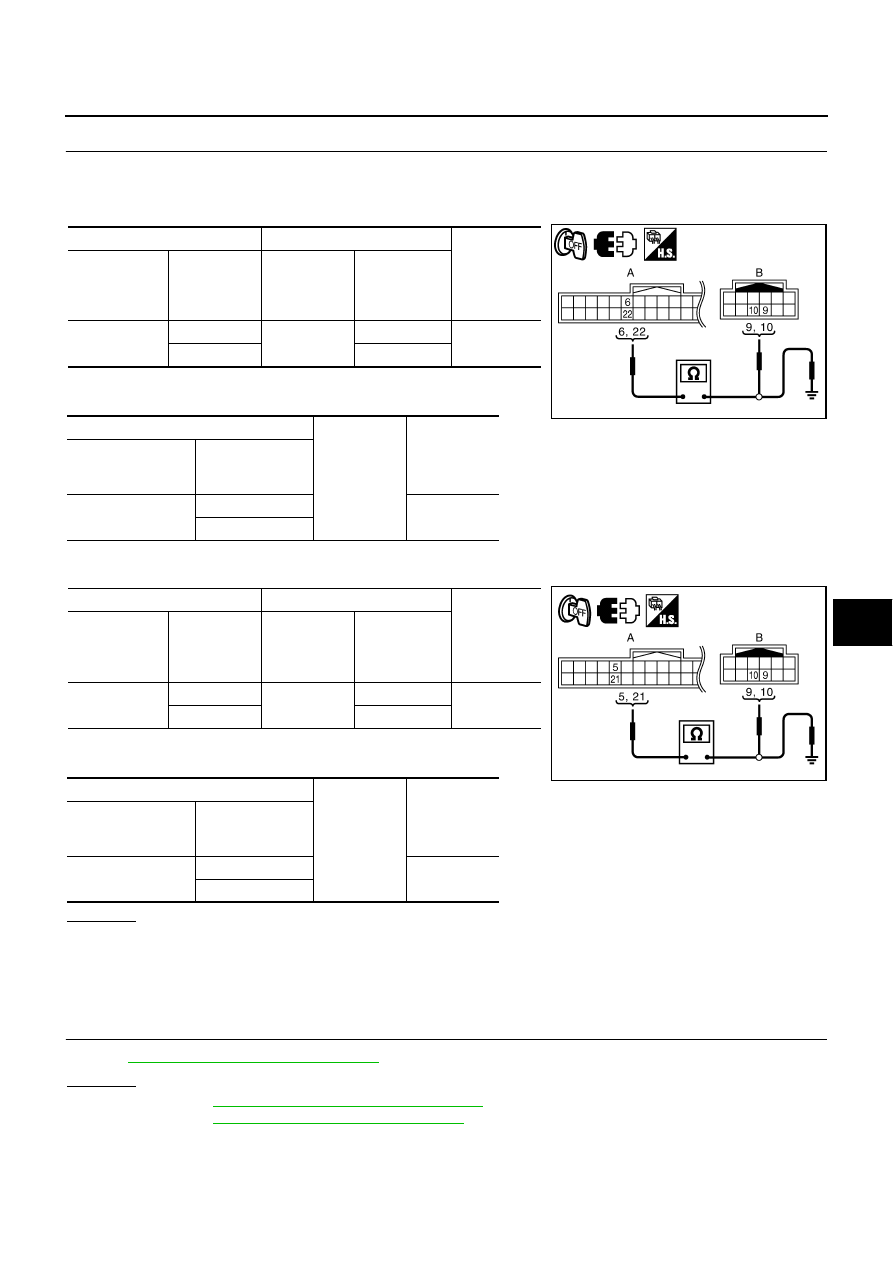
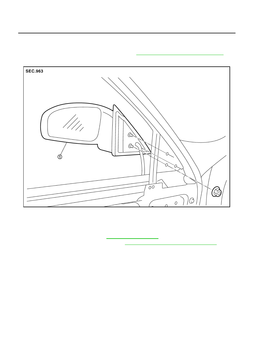
CHECK HARNESS CONTINUITY 3
1.
Disconnect automatic drive positioner control unit connector and door mirror connector.
2.
[Door mirror LH]
–
Check continuity between automatic drive positioner control unit connector and door mirror LH connector.
–
Check continuity between automatic drive positioner control unit
connector and ground.
3.
[Door mirror RH]
–
Check continuity between automatic drive positioner control unit connector and door mirror RH connector.
–
Check continuity between automatic drive positioner control unit
connector and ground.
OK or NG
OK
>> Check the condition of harness and connector.
NG
>> Repair or replace harness between automatic drive positioner control unit and door mirror con-
nector.
Check A/T Control Device R Position Circuit
NIS0023F
1.
CHECK R POSITION SIGNAL
Refer to
AT-186, "A/T INDICATOR CIRCUIT"
OK or NG
OK
>> Refer to
SE-37, "SELF-DIAGNOSIS RESULTS"
NG
>> Refer to
AT-186, "A/T INDICATOR CIRCUIT"
A
B
Continuity
Automatic
drive posi-
tioner control
unit connector
Terminal
Door mirror
LH connector
Terminal
M6
6
D2
9
Yes
22
10
A
Ground
Continuity
Automatic drive
positioner control
unit connector
Terminal
M6
6
No
22
A
B
Continuity
Automatic
drive posi-
tioner control
unit connector
Terminal
Door mirror
RH connector
Terminal
M6
5
D39
9
Yes
21
10
A
Ground
Continuity
Automatic drive
positioner control
unit connector
Terminal
M6
5
No
21
PIIB6036E
PIIB6030E
GW-118
DOOR MIRROR
DOOR MIRROR
PFP:96301
Automatic Drive Positioner Interlocking Door Mirror
NIS0023G
Automatic drive positioner interlocking door mirror. Refer to
SE-11, "AUTOMATIC DRIVE POSITIONER"
.
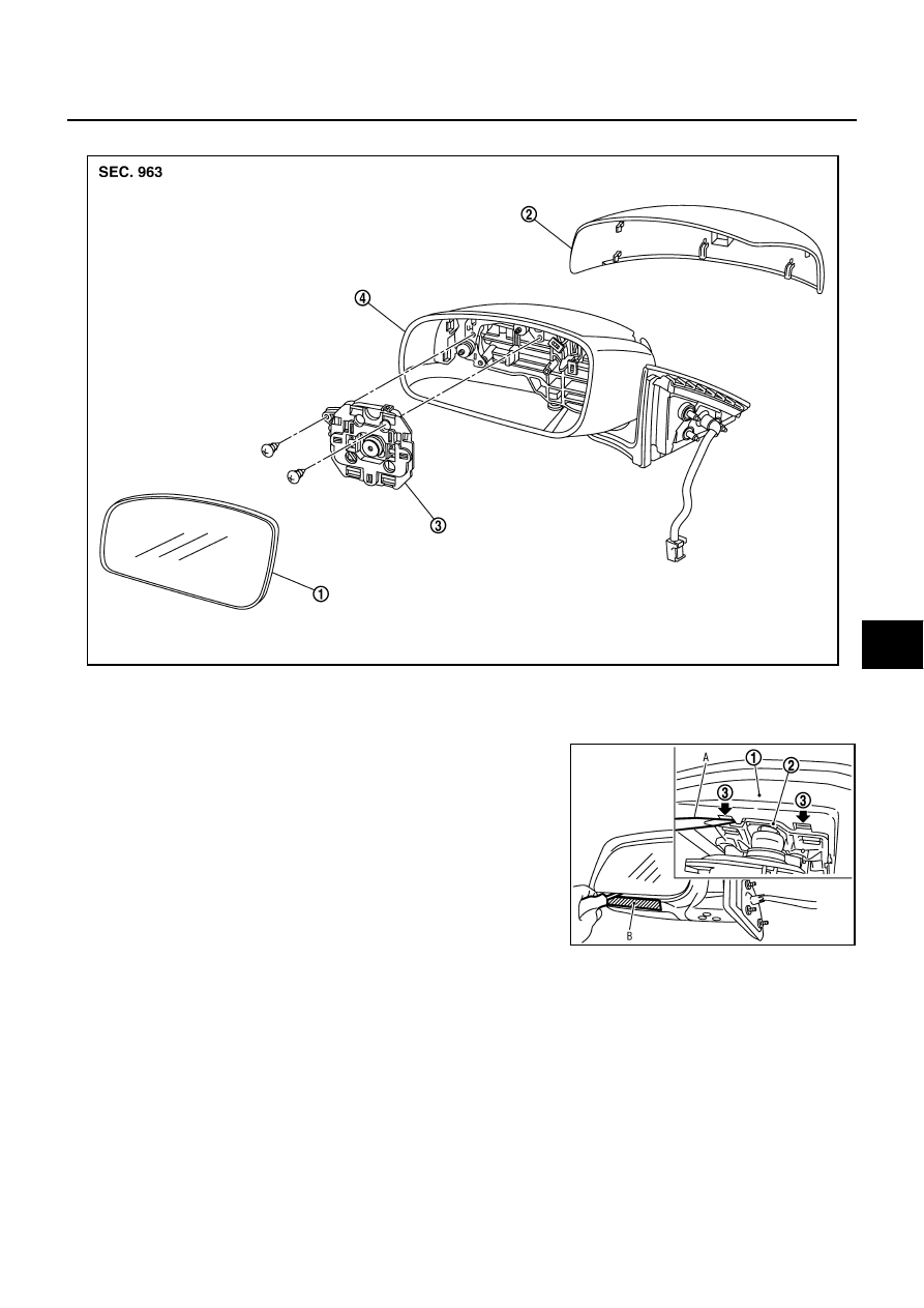
Removal and Installation
NIS0023H
CAUTION:
Be careful not to damage the mirror bodies.
REMOVAL
1.
Remove the front door finisher. Refer to
2.
Remove the front door sash cover inner. Refer to
EI-36, "FRONT DOOR SASH COVER INNER"
.
3.
Remove the door mirror harness connector.
4.
Remove the door mirror mounting nuts, and remove the door mirror assembly.
INSTALLATION
Install in the reverse order of removal.
1.
Door mirror assembly
PIIB3300J
DOOR MIRROR
GW-119
C
D
E
F
G
H
J
K
L
M
A
B
GW
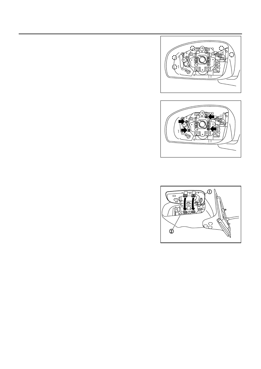
Disassembly and Assembly
NIS0023I
DISASSEMBLY
1.
Place the mirror body with mirror glass facing upward.
2.
Put a strip of protective tape B on mirror body.
3.
As shown in the figure, insert a small slotted screwdriver A into
the recess between mirror base (mirror holder)(1) and mirror
holder bracket (2) and push up two pawls (3) to remove mirror
holder lower half side.
NOTE:
When pushing up pawls do not attempt to use one recess only,
be sure to push up with both recesses.
Insert screwdriver into recesses, and push up while rotating
(twist) to make work easier.
4.
Remove two terminals of mirror heater attachment.
5.
Lightly lift up lower side of mirror surface from mirror surface, and detach two pawls of upper side as if
pulling it out. Remove mirror surface from mirror body.
NOTE:
Be certain not to allow grease on sealing agent in center of mirror body assembly (actuator) or back side
of mirror surface (mirror holder).
1.
Mirror housing
2.
Mirror cover
3.
Power unit
4.
Mirror (mirror holder)
PIIB5782E
PIIB8320J
GW-120
DOOR MIRROR
6.
Remove the clips and mirror cover from the housing.
7.
Remove the screws and power unit from the housing.
ASSEMBLY
1.
Install the power unit.
2.
Install the mirror cover.
3.
Place mirror holder bracket and mirror body assembly (actuator) in a horizontal position.
4.
Connect two terminals of heater installed mirror.
5.
Fit the upper two pawls on the mirror face (1) onto the mirror
holder bracket (2) first, then press the lower side of mirror face
until a click sound is heard to engage the lower pawls.
NOTE:
After installation, visually make sure lower two pawls are
securely engaged from the bottom of mirror face.
PIIB3302J
PIIB3303J
PIIB3306J
Нет комментариевНе стесняйтесь поделиться с нами вашим ценным мнением.
Текст