Infiniti M35/M45 Y50. Manual — part 828
REVERSE INTERLOCK DOOR MIRROR SYSTEM
GW-109
C
D
E
F
G
H
J
K
L
M
A
B
GW
5.
CHECK AUTOMATIC DRIVE POSITIONER CONTROL UNIT OUTPUT SIGNAL
1.
Connect automatic drive positioner control unit connector.
2.
Turn ignition switch ON.
3.
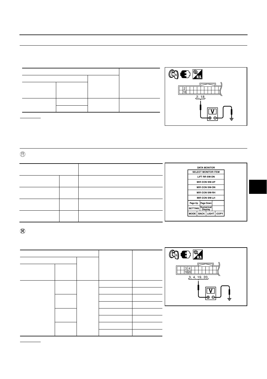
Check voltage between automatic drive positioner control unit connector and ground.
OK or NG
OK
>> Check the condition of harness and connector.
NG
>> Replace automatic drive positioner control unit.
Check Mirror Switch Circuit
NIS0023C
1.
CHECK MIRROR SWITCH SIGNAL
With CONSULT-II
Check the operation on “(MIR CON SW–UP/DN) and (MIR CON SW–RH/LH) in the DATA MONITOR.
Without CONSULT-II
1.
Turn ignition switch to ON position.
2.
Check voltage between automatic drive positioner control unit connector and ground.
OK or NG
OK
>> Mirror switch circuit is OK.
NG
>> GO TO 2.
Terminals
Voltage (V)
(Approx.)
(+)
(-)
Automatic drive
positioner control
unit connector
Terminal
M6
2
Ground
5
18
PIIB6015E
Monitor item
[OPERATION or UNIT]
Contents
MIR CON SW–UP
“ON/
OFF”
ON/OFF status judged from the mirror switch
(UP) signal is displayed.
MIR CON SW–DN
“ON/
OFF”
ON/OFF status judged from the mirror switch
(DOWN) signal is displayed.
MIR CON SW–RH
“ON/
OFF”
ON/OFF status judged from the mirror switch
(RIGHT) signal is displayed.
MIR CON SW–LH
“ON/
OFF”
ON/OFF status judged from the mirror switch
(LEFT) signal s displayed.
PIIA0199E
Terminals
Mirror switch
Condition
Voltage (V)
(Approx.)
(+)
(–)
Automatic drive
positioner control
unit connector
Terminal
M6
3
Ground
UP
0
Other than above
5
4
LEFT
0
Other than above
5
19
DOWN
0
Other than above
5
20
RIGHT
0
Other than above
5
PIIB6019E
GW-110
REVERSE INTERLOCK DOOR MIRROR SYSTEM
2.
CHECK HARNESS CONTINUITY
1.
Turn ignition switch OFF.
2.
Disconnect automatic drive positioner control unit and door mirror remote control switch connector.
3.
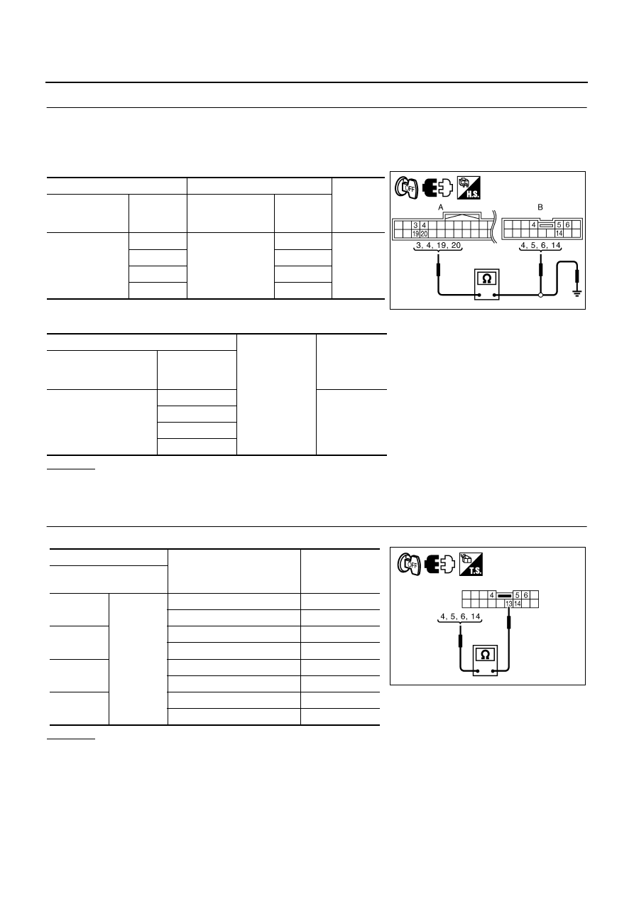
Check continuity between automatic drive positioner control unit connector and door mirror remote control
switch connector.
4.
Check continuity between automatic drive positioner control unit
connector and ground.
OK or NG
OK
>> GO TO 3.
NG
>> Repair or replace harness.
3.
CHECK DOOR MIRROR SWITCH
Check door mirror remote control switch.
OK or NG
OK
>> GO TO 4.
NG
>> Replace door mirror remote control switch.
A
B
Continuity
Automatic drive
positioner control
unit connector
Terminal
Door mirror remote
control switch
connector
Terminal
M6
3
M95
6
Yes
4
5
19
14
20
4
A
Ground
Continuity
Automatic drive posi-
tioner control unit con-
nector
Terminal
M6
3
No
4
19
20
PIIB6020E
Terminal
Mirror switch condition
Continuity
Door mirror remote
control switch
4
13
RIGHT
Yes
Other than above
No
5
LEFT
Yes
Other than above
No
6
UP
Yes
Other than above
No
14
DOWN
Yes
Other than above
No
PIIB6021E
REVERSE INTERLOCK DOOR MIRROR SYSTEM
GW-111
C
D
E
F
G
H
J
K
L
M
A
B
GW
4.
CHECK AUTOMATIC DRIVE POSITIONER CONTROL UNIT OUTPUT SIGNAL
1.
Connect automatic drive positioner control unit connector.
2.
Turn ignition switch ON.
3.
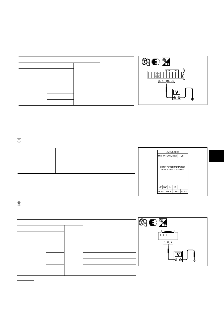
Check voltage between automatic drive positioner control unit and ground.
OK or NG
OK
>> Check the condition of harness and connector.
NG
>> Replace automatic drive positioner control unit.
Check Mirror Motor Circuit
NIS0023D
1.
CHECK MIRROR MOTOR FUNCTION
With CONSULT-II
Check the operation with (MIRROR MOTOR RH, MIRROR MOTOR LH) in the ACTIVE TEST.
Without CONSULT-II
1.
Turn ignition switch to ON position.
2.
Check voltage between door mirror connector and ground.
OK or NG
OK
>> Mirror motor circuit is OK.
NG
>> GO TO 2.
Terminals
Voltage (V)
(Approx.)
(+)
(-)
Automatic drive
positioner control
unit connector
Terminal
M6
3
Ground
5
4
19
20
PIIB6019E
Test item
Description
MIRROR MOTOR LH
The LH mirror motor moves the mirror UP/DOWN and
LEFT/RIGHT by receiving the drive signal.
MIRROR MOTOR RH
The RH mirror motor moves the mirror UP/DOWN and
LEFT/RIGHT by receiving the drive signal.
PIIB6022E
Terminals
Mirror switch
Condition
Voltage (V)
(Approx.)
(+)
(–)
Door mirror
connector
Terminal
D2 (RH)
D39 (LH)
5
Ground
UP
Battery voltage
Other than above
0
6
LEFT
Battery voltage
Other than above
0
7
DOWN / RIGHT
Battery voltage
Other than above
0
PIIB6031E
GW-112
REVERSE INTERLOCK DOOR MIRROR SYSTEM
2.
CHECK HARNESS CONTINUITY
1.
Turn ignition switch OFF.
2.
Disconnect automatic drive positioner control unit connector and door mirror connector.
3.
[Door mirror LH]
–
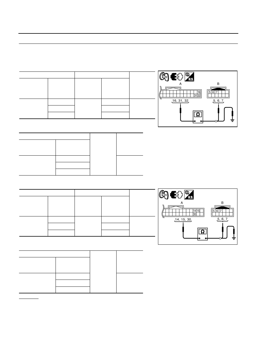
Check continuity between automatic drive positioner control unit connector and door mirror LH connector.
–
Check continuity between automatic drive positioner control unit
connector and ground.
4.
[Door mirror RH]
–
Check continuity between automatic drive positioner control unit connector and door mirror RH connector.
–
Check continuity between automatic drive positioner control unit
connector and ground.
OK or NG
OK
>> GO TO 3.
NG
>> Repair or replace harness.
A
B
Continuity
Automatic
drive posi-
tioner control
unit connector
Terminal
Door mirror
LH connector
Terminal
M6
16
D2
7
Yes
31
5
32
6
A
Ground
Continuity
Automatic drive
positioner control
unit connector
Terminal
M6
16
No
31
32
A
B
Continuity
Automatic
drive posi-
tioner control
unit connector
Terminal
Door mirror
RH connector
Terminal
M6
14
D39
5
Yes
15
6
30
7
A
Ground
Continuity
Automatic drive
positioner control
unit connector
Terminal
M6
14
No
15
30
PIIB6023E
PIIB6024E
Нет комментариевНе стесняйтесь поделиться с нами вашим ценным мнением.
Текст