Infiniti M35/M45 Y50. Manual — part 1060
AUTOMATIC DRIVE POSITIONER
SE-37
C
D
E
F
G
H
J
K
L
M
A
B
SE
CONSULT-II Function (AUTO DRIVE POS.)
NIS00260
CONSULT-II can display each diagnostic item using the diagnostic test modes shown following.
CONSULT-II START PROCEDURE
Refer to
GI-38, "CONSULT-II Start Procedure"
.
SELF-DIAGNOSIS RESULTS
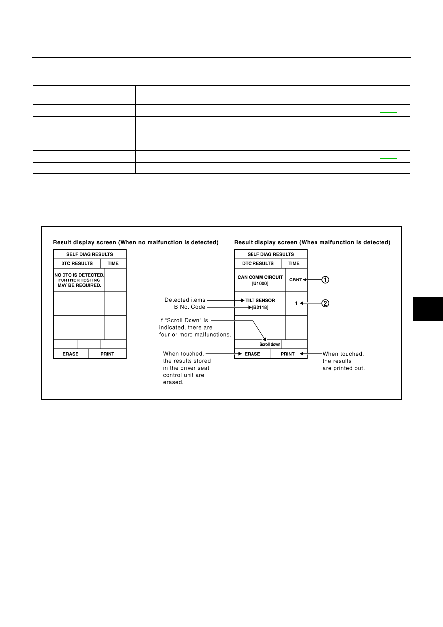
HOW TO READ SELF-DIAG RESULTS
NOTE:
●
CAN communication malfunction and detention switch malfunction are displayed on “TIME”. (1)
–
If error is detected in the present, “CRNT” is displayed.
–
If error is detected in the past (present error is not detected), “PAST” is displayed.
–
If error has never been detected, nothing is displayed on “TIME”.
●
Any items other than CAN communication malfunction and detention switch malfunction are counted. (2)
–
If error is detected, error detection frequency is displayed from “1” to “127” on “TIME”.
–
If error has never been detected, nothing is displayed on “TIME”.
–
Can clear the detected memory.
Normal: Clear memory in normal condition, history is erased and nothing is displayed on “TIME”.
Error: Clear memory in error condition, error is detected again and “1” is displayed on “TIME”.
AUTO DRIVE POS.
diagnostic mode
Description
Reference
page
WORK SUPPORT
Changes settings for each function.
SELF-DIAG RESULTS
Displays driver seat control unit self-diagnosis results.
DATA MONITOR
Displays driver seat control unit input/output data in real time.
CAN DIAG SUPPORT MNTR
The result of transmit/receive diagnosis of CAN communication can be read.
ACTIVE TEST
Operation of electrical loads can be checked by sending drive signal to them.
ECU PART NUMBER
Driver seat control unit part number can be read.
—
PIIB6449E

SE-38
AUTOMATIC DRIVE POSITIONER
DISPLAY ITEM LIST
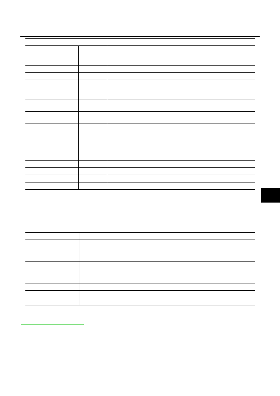
DATA MONITOR
SELECTIOM FROM MEMU
DTC
Self-diagnosis item
(CONSULT-II indication)
DTC detection condition
Reference
page
U1000
CAN COMM CIRCUIT
When driver seat control unit is not transmitting or receiving CAN communication
signal for 2 seconds or more.
B2112
SEAT SLIDE
When any manual and automatic operations are not performed, if any motor
operations of seat slide is detected for 0.1 second or more, status is judged “Out-
put error”.
B2113
SEAT RECLINING
When any manual and automatic operations are not performed, if any motor
operations of seat reclining is detected for 0.1 second or more, status is judged
“Output error”.
B2114
SEAT LIFTER-FR
When any manual and automatic operations are not performed, if any motor
operations of seat lifting FR is detected for 0.1 second or more, status is judged
“Output error”.
B2115
SEAT LIFTER-RR
When any manual and automatic operations are not performed, if any motor
operations of seat lifting RR is detected for 0.1 second or more, status is judged
“Output error”.
B2116
STEERING TILT
When any manual and automatic operations are not performed, if any motor
operations of steering tilt is detected for 0.1 second or more, status is judged
“Output error”.
B2118
STRG TILT SENSOR
When driver seat control unit detects 0.1V or lower, or 4.9V or higher, from tilt
sensor for 0.5 seconds or more.
B2119
STEERING TELESCO
When driver seat control unit detects 0.1V or lower, or 4.9V or higher, from
telescopic sensor for 0.5 seconds or more.
B2126
DETENT SW
With the A/T selector lever in P position (Detente switch OFF), if the vehicle
speed of 7 km/h (4 MPH) or higher was input the detention switch input system is
judged malfunctioning.
B2128
UART COMM
Malfunction is detected in UART communication.
Monitor item [OPERATION or UNIT]
Contents
SET SW
“ON/OFF”
ON/OFF status judged from the setting switch signal is displayed.
MEMORY SW1
“ON/OFF”
ON/OFF status judged from the seat memory switch 1 signal is displayed.
MEMORY SW2
“ON/OFF”
ON/OFF status judged from the seat memory switch 2 signal is displayed.
SLIDE SW–FR
“ON/OFF”
ON/OFF status judged from the sliding switch (FR) signal is displayed.
SLIDE SW–RR
“ON/OFF”
ON/OFF status judged from the sliding switch (RR) signal is displayed.
RECLN SW–FR
“ON/OFF”
ON/OFF status judged from the reclining switch (FR) signal is displayed.
RECLN SW–RR
“ON/OFF”
ON/OFF status judged from the reclining switch (RR) signal is displayed.
LIFT FR SW–UP
“ON/OFF”
ON/OFF status judged from the FR lifting switch (UP) signal is displayed.
LIFT FR SW–DN
“ON/OFF”
ON/OFF status judged from the FR lifting switch (DOWN) signal is displayed.
LIFT RR SW–UP
“ON/OFF”
ON/OFF status judged from the RR lifting switch (UP) signal is displayed.
LIFT RR SW–DN
“ON/OFF”
ON/OFF status judged from the RR lifting switch (DOWN) signal is displayed.
MIR CON SW–UP
“ON/OFF”
ON/OFF status judged from the door mirror remote control switch (UP) signal is
displayed.
MIR CON SW–DN
“ON/OFF”
ON/OFF status judged from the door mirror remote control switch (DOWN) signal
is displayed.
MIR CON SW–RH
“ON/OFF”
ON/OFF status judged from the door mirror remote control switch (RIGHT) signal
is displayed.
MIR CON SW–LH
“ON/OFF”
ON/OFF status judged from the door mirror remote control switch (LEFT) signal is
displayed.
MIR CHNG SW–R
“ON/OFF”
ON/OFF status judged from the door mirror remote control switch (switching to
RIGHT) signal is displayed.
AUTOMATIC DRIVE POSITIONER
SE-39
C
D
E
F
G
H
J
K
L
M
A
B
SE
ACTIVE TEST
CAUTION:
During vehicle driving, do not perform active test.
NOTE:
If active test is performed, reset seat memory and key fob interlock drive positioner after performing work.
DISPLAY ITEM LIST
WORK SUPPORT
The seat slide amount at entry/exit operation setting can be changed by CONSULT-II. Refer to
.
MIR CHNG SW–L
“ON/OFF”
ON/OFF status judged from the door mirror remote control switch (switching to
LEFT) signal is displayed.
TILT SW-UP
“ON/OFF”
ON/OFF status judged from the tilt switch (UP) signal is displayed.
TILT SW-DOWN
“ON/OFF”
ON/OFF status judged from the tilt switch (DOWN) signal is displayed.
TELESCO SW-FR
“ON/OFF”
ON/OFF status judged from the telescoping switch (FR) signal is displayed.
TELESCO SW-RR
“ON/OFF”
ON/OFF status judged from the telescoping switch (RR) signal is displayed.
DETENT SW
“ON/OFF”
The selector lever position “OFF (P position) / ON (other than P position)” judged
from the detention switch signal is displayed.
STARTER SW
“ON/OFF”
Ignition key switch ON (START, ON) /OFF (IGN, ACC, or OFF) status judged from
the ignition switch signal is displayed.
SLIDE PULSE
—
Value (32768) when battery connects is as standard. If it moves backward, the
value increases. If it moves forward, the value decreases.
RECLN PULSE
—
Value (32768) when battery connects is as standard. If it moves backward, the
value increases. If it moves forward, the value decreases.
LIFT FR PULSE
—
Value (32768) when battery connects is as standard. If it moves DOWN, the value
increases. If it moves UP, the value decreases.
LIFT RR PULSE
—
Value (32768) when battery connects is as standard. If it moves DOWN, the value
increases. If it moves UP, the value decreases.
MIR/SEN RH U–D
“V”
Voltage output from RH door mirror sensor (UP/DOWN) is displayed.
MIR/SEN RH R–L
“V”
Voltage output from RH door mirror sensor (LH/RH) is displayed.
MIR/SEN LH U–D
“V”
Voltage output from LH door mirror sensor (UP/DOWN) is displayed.
MIR/SEN LH R–L
“V”
Voltage output from LH door mirror sensor (LH/RH) is displayed.
Monitor item [OPERATION or UNIT]
Contents
Test item
Description
TILT MOTOR
The tilt motor is activated by receiving the drive signal.
TELESCO MOTOR
The telescopic motor is activated by receiving the drive signal.
SEAT SLIDE
The sliding motor is activated by receiving the drive signal.
SEAT RECLINING
The reclining motor is activated by receiving the drive signal.
SEAT LIFTER FR
The front lifting motor is activated by receiving the drive signal.
SEAT LIFTER RR
The rear lifting motor is activated by receiving the drive signal.
MIRROR MOTOR RH
The RH mirror motor moves the mirror UP/DOWN and LEFT/RIGHT by receiving the drive signal.
MIRROR MOTOR LH
The LH mirror motor moves the mirror UP/DOWN and LEFT/RIGHT by receiving the drive signal.
MEMORY SW INDCTR
The memory switch indicator is lit by receiving the drive signal.

SE-40
AUTOMATIC DRIVE POSITIONER
Work Flow
NIS00261
1.
Check the symptom and customer's requests.
2.
Understand the system description. Refer to
3.
Perform the self-diagnosis results, using CONSULT-II. Refer to
SE-37, "CONSULT-II Function (AUTO
4.
Repair or replace depending on the self-diagnostic results.
5.
Based on the trouble diagnosis chart, repair or replace the cause of the malfunction. Refer to
6.
Does the automatic drive positioned system operate normally?
If it is normal, GO TO 8.
If it is not normal, GO TO 3.
7.
INSPECTION END
Symptom Chart
NIS00262
NOTE:
Always check the “Work flow” before performing diagnosis in the following table, Refer to
.
Symptom
Diagnoses / service procedure
Reference
page
All of automatic operation dose not operate.
1. Check BCM power supply and ground circuit
2. Check driver seat control unit power supply and
ground circuit
3. Check automatic drive positioner control unit
power supply and ground circuit
Sliding function does not operate (automatically and manually).
Check sliding motor circuit
Reclining function does not operate (automatically and manually).
Check reclining motor circuit
Front lifting function does not operate
(automatically and manually).
Check front lifting motor circuit
Rear lifting function not operate (automatically and manually).
Check rear lifting motor circuit
Tilt function does not operate (automatically and manually).
Check tilt motor circuit
Telescopic function does not operate
(automatically and manually).
Check telescopic motor circuit
Sliding function does not operate automatically.
Check sliding sensor circuit
Reclining function does not operate automatically.
Check reclining sensor circuit
Front lifting function does not operate automatically.
Check front lifting sensor circuit
Rear lifting function does not operate automatically.
Check rear lifting sensor circuit
Tilt function does not operate automatically.
Check tilt sensor circuit
Telescopic function does not operate automatically.
Check telescopic sensor circuit
Sliding function does not operate manually.
Check sliding switch circuit
Reclining function does not operate manually.
Check reclining switch circuit
Front lifting function does not operate manually.
Check lifting switch (front) circuit
Rear lifting function does not operate manually.
Check lifting switch (rear) circuit
Tilt function does not operate manually.
Check tilt switch circuit
Telescopic function does not operate manually.
Check telescopic switch circuit
All of seat operation dose not operate manually.
Check power seat switch ground circuit
Only seat memory and set switch operation does not operate.
1. Perform storing memory
2. Check seat memory and set switch circuit
Seat memory indicator lamps 1 and 2 do not illuminate.
Check seat memory indicator lamp circuit
Нет комментариевНе стесняйтесь поделиться с нами вашим ценным мнением.
Текст