Infiniti M35/M45 Y50. Manual — part 1061

AUTOMATIC DRIVE POSITIONER
SE-41
C
D
E
F
G
H
J
K
L
M
A
B
SE
Entry/Exiting operation does not operated.
1. Check system setting
2. Perform initialization
3. Check front door switch (driver side) circuit
LH or RH door mirror face does not produce the stored angle,
during the memory operation.
1. Check door mirror sensor power supply and
ground circuit
2. Check door mirror sensor LH circuit
3. Check door mirror sensor RH circuit
4. Replace automatic drive positioner control unit
Intelligent key interlock operation does not operate.
(Other automatic operation and Intelligent Key system are normal)
Perform storing memory
Lumbar support does not operate
Check Lumbar support circuit
Symptom
Diagnoses / service procedure
Reference
page

SE-42
AUTOMATIC DRIVE POSITIONER
CAN Communication Inspection Using CONSULT-II (Self-Diagnosis)
NIS00263
1.
SELF-DIAGNOSTIC RESULT CHECK
CAUTION:
If CONSULT-II is used with no connection of CONSULT-II CONVERTER, malfunctions might be
detected in self-diagnosis depending on control unit which carry out CAN communication.
1.
Connect to CONSULT-II, and select “AUTO DRIVE POS.” on the “SELECT DIAG SYSTEM” screen.
2.
Select “SELF-DIAG RESULTS” on “SELECT DIAG MODE” screen.
3.
Check display content in self-diagnostic results.
Contents displayed
No malfunction>>Inspection End.
Malfunction in CAN communication system>>After printing the monitor items, go to “CAN System”. Refer to
LAN-50, "CAN System Specification Chart"
Check BCM Power Supply and Ground Circuit
NIS00264
1.
CHECK FUSE
Check if any of the following fuses in the BCM are blown.
SE-11, "Component Parts And Harness Connector Location"
OK or NG
OK
>> GO TO 2.
NG
>> If fuse is blown, be sure to eliminate cause of malfunction before installing new fuse. Refer to
3, "POWER SUPPLY ROUTING CIRCUIT"
CONSULT-II display code
Diagnosis item
U1000
INITIAL DIAG
TRANSMIT DIAG
BCM/SEC
METER/M&A
TCM
Unit
Power source
Fuse No.
BCM
Battery power supply
F (50A)
Battery power supply
21 (10A)
Ignition switch ON or STRAT signal
1 (15A)
Ignition switch ACC or ON signal
6 (10A)
AUTOMATIC DRIVE POSITIONER
SE-43
C
D
E
F
G
H
J
K
L
M
A
B
SE
2.
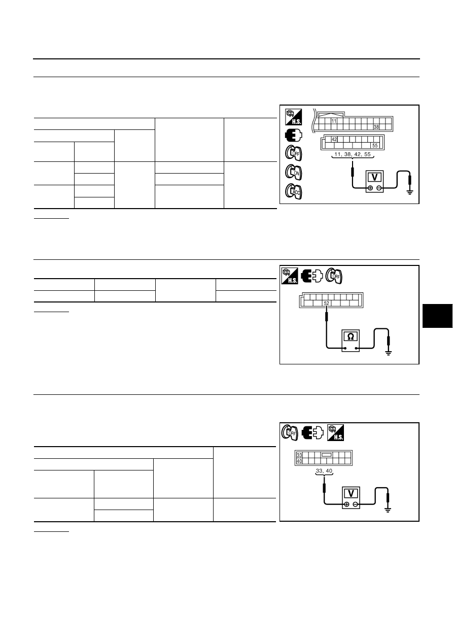
CHECK POWER SUPPLY CIRCUIT (BCM)
1.
Turn ignition switch OFF.
2.
Disconnect BCM connector.
3.
Check voltage between BCM connector and ground.
OK or NG
OK
>> GO TO 3.
NG
>> Repair or replace the harness between BCM and fuse.
3.
CHECK GROUND CIRCUIT (BCM)
Check continuity between BCM connector and ground.
OK or NG
OK
>> BCM power supply and ground circuit are OK.
NG
>> Repair or replace the harness between BCM and
ground.
Check Driver Seat Control Unit Power Supply and Ground Circuit
NIS00265
1.
CHECK POWER SUPPLY CIRCUIT
1.
Turn ignition switch OFF.
2.
Disconnect driver seat control unit connector.
3.
Check voltage between driver seat control unit connector and
ground.
OK or NG
OK
>> GO TO 2.
NG
>> Check the following.
●
Repair or replace harness between driver seat control unit and fuse block (J/B).
●
Circuit breaker.
Terminals
Condition of
ignition switch
Voltage (V)
(Approx.)
(+)
(–)
BCM
connector
Terminal
M1
38
Ground
ON
Battery voltage
11
ACC
M2
42
OFF
55
PIIB6296E
BCM connector
Terminal
Ground
Continuity
M2
52
Yes
PIIB5935E
Terminals
Voltage (V)
(Approx.)
(+)
(–)
Driver seat
control unit
connector
Terminal
B205
33
Ground
Battery voltage
40
PIIB6128E
SE-44
AUTOMATIC DRIVE POSITIONER
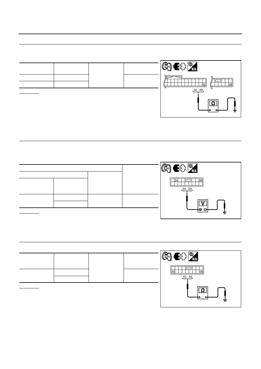
2.
CHECK GROUND CIRCUIT
1.
Turn ignition switch OFF.
2.
Check continuity between the driver seat control unit connector and ground.
OK or NG
OK
>> Driver seat control unit power supply and ground circuit
are OK.
NG
>> Repair or replace harness between driver seat control
unit and ground.
Check Automatic Drive Positioner Control Unit Power Supply and Ground Cir-
cuit
NIS00266
1.
CHECK POWER SUPPLY CIRCUIT
1.
Turn ignition switch OFF.
2.
Disconnect automatic drive positioner control unit connector.
3.
Check voltage between automatic drive positioner control unit connector and ground.
OK or NG
OK
>> GO TO 2.
NG
>> Repair or replace harness between automatic drive
positioner control unit and fuse block (J/B).
2.
CHECK GROUND CIRCUIT
Check continuity between the automatic drive positioner control unit connector and ground.
OK or NG
OK
>> Automatic drive positioner control unit power supply and
ground circuit are OK.
NG
>> Repair or replace harness between automatic drive
positioner control unit and ground.
Driver seat control
unit connector
Terminal
Ground
Continuity
B204
32
Yes
B205
48
PIIB6129E
Terminals
Voltage (V)
(Approx.)
(+)
(–)
Automatic drive
positioner control
unit connector
Terminal
M7
34
Ground
Battery voltage
39
PIIB6130E
Automatic drive
positioner control
unit connector
Terminal
Ground
Continuity
M7
40
Yes
48
PIIB6131E
Нет комментариевНе стесняйтесь поделиться с нами вашим ценным мнением.
Текст