Mitsubishi Lancer Evolution IX. Manual — part 570
AC504564
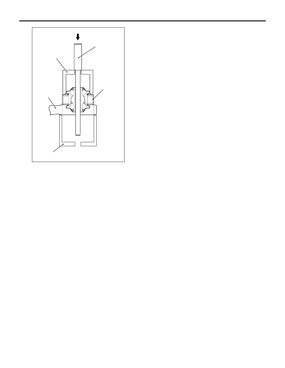
MB990651
MB991576
Lower arm
assembly
MB991816
AB
Outer tube
LOWER ARM
FRONT SUSPENSION
33-13
3. Use special tools to press in the bushing until its
outer tube is flush with the lower arm assembly
surface.

STABILIZER BAR
FRONT SUSPENSION
33-14
STABILIZER BAR
REMOVAL AND INSTALLATION
M1332004000662
CAUTION
• Before removing the steering wheel and air bag module assembly, refer to GROUP 52B − Service
Precautions (
) and Driver’s, Front Passenger’s Air Bag Module(s) and Clock Spring
(
). Also, put the front wheels in straight-ahead position. Failure to do so may damage the
SRS clock spring and render the SRS air bag inoperative, which results serious driver injury.
• During maintenance, take care not to contact the parts or tools to the caliper because the paint of
caliper will be scratched. And if there is brake fluid on the caliper, wipe off quickly.
•
Pre-removal Operation
• Steering Wheel - Driver’s Air Bag Module Assembly
Removal (Refer to GROUP 37, Steering Wheel
• Clock Spring Removal (Refer to GROUP 52B, Driver’s,
Front Passenger’s Air Bag Module(s) and Clock Spring
).
• Front Axle Crossmember Bar Removal (Refer to
• Front Axle No.1 Crossmember Assembly Removal (Refer
to GROUP 32, Crossmember
• Front Exhaust Pipe Removal (Refer to GROUP 15,
Exhaust Pipe and Main Muffler
Post-installation Operation
• Front Exhaust Pipe Installation (Refer to GROUP 15,
Exhaust Pipe and Main Muffler
• Front Axle No.1 Crossmember Assembly Installation
(Refer to GROUP 32, Crossmember
).
• Front Axle Crossmember Bar Installation (Refer to
• Clock Spring Installation (Refer to GROUP 52B, Driver’s,
Front Passenger’s Air Bag Module(s) and Clock Spring
).
• Steering Wheel - Driver’s Air Bag Module Assembly
Installation (Refer to GROUP 37, Steering Wheel
• Check the Dust Cover for Cracks or Damage by Pushing
it with Finger.
• Checking Steering Wheel Position with Wheels Straight
Ahead
• Front Wheel Alignment Check and Adjustment (Refer to
).
*
: Indicates parts which should be temporarily tightened, and then fully tightened with the vehicle
on the ground in an unladen condition.

AC310741AB
7
N
25 ± 5 N·m
39 ± 5 N·m
1
108 ± 10 N·m
49 ± 10 N·m
167 ± 9 N·m
52 ± 7 N·m*
9
8
21 ± 4 N·m
5
18 ± 2 N·m
6
10
4
3
39 ± 5 N·m
Removal steps
1.
Stabilizer link
2.
Stabilizer bar bracket
3.
Lower arm and knuckle
connection
<<
A
>>
4.
Tie rod end knuckle
connection
5.
Steering shaft cover
6.
Steering gear and joint
connection bolt
7.
Rear roll stopper connection
bolt
<<
B
>>
>>
A
8.
Stabilizer bracket
<<
B
>>
>>
A
9.
Stabilizer bushing
<<
B
>>
>>
A
10.
Stabilizer bar
STABILIZER BAR
FRONT SUSPENSION
33-15
Removal steps (Continued)
STABILIZER BAR
FRONT SUSPENSION
33-16
REMOVAL SERVICE POINTS
<<A>> TIE ROD END AND KNUCKLE DIS-
CONNECTION
CAUTION
• Do not remove the nut from ball joint. Loosen
it and use special tool ball joint remover
(MB991897 or MB992011) to avoid possible
damage to ball joint threads.
• Hang special tool ball joint remover
(MB991897 or MB992011) with a cord to pre-
vent it from falling.
AC208247AJ
Cord
Bolt
MB991897
or
MB992011
Nut
Ball joint
1. Install special tool ball joint remover (MB991897
or MB992011) as shown in the figure.
AC106821
Knob
Parallel
Bolt
Good
Bad
AB
2. Turn the bolt and knob as necessary to make the
jaws of special tool ball joint remover (MB991897
or MB992011) parallel, tighten the bolt by hand
and confirm that the jaws are still parallel.
NOTE: When adjusting the jaws in parallel, make
sure the knob is in the position shown in the fig-
ure.
3. Tighten the bolt with a wrench to disconnect the
tie rod end.
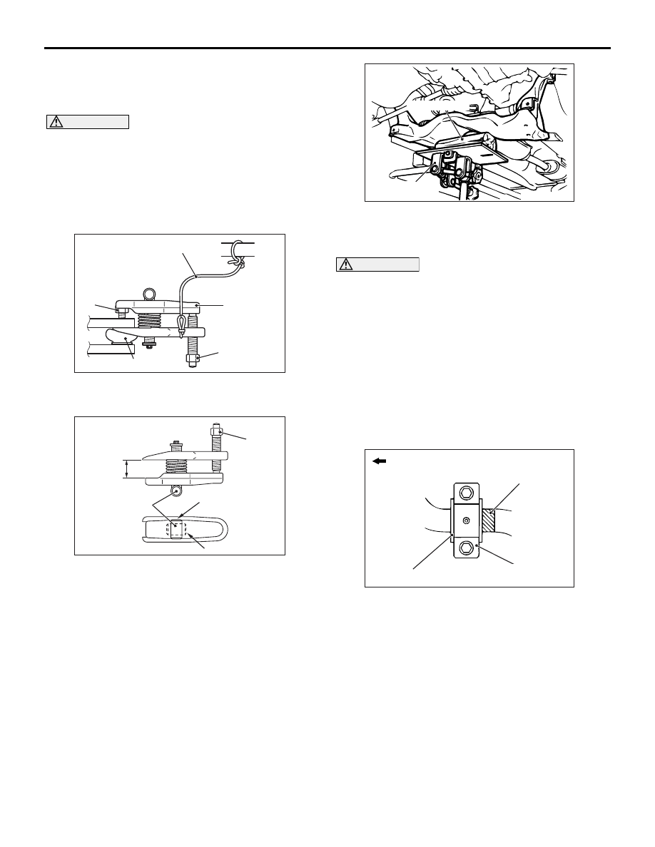
<<B>> STABILIZER
BRACKET/STABILIZER
BUSHING/STABILIZER BAR REMOVAL
Carry out the following operations to ensure working
space in order to remove the fixture, the bushing and
the stabilizer bar.
AC102600 AD
Piece of wood
Transmission
jack
1. Use a transmission jack to hold the crossmember,
remove the crossmember mounting nuts and
bolts.
CAUTION
Be careful not to lower the crossmember exces-
sively. The power steering return hose bracket
may deform if the crossmember is lowered too
much.
2. Lower the crossmember until the fixture, the
bushing and the stabilizer bar can be removed.
INSTALLATION SERVICE POINTS
>>A<< STABILIZER BAR/STABILIZER
BUSHING/STABILIZER
BRACKET/INSTALLATION
AC006141AJ
Outside of vehicle
Stabilizer bushing (LH)
Identification mark
Stabilizer bracket (LH)
Align the stabilizer bar identification mark with the
right end of the bushing (LH).
INSPECTION
M1332002000321
• Check the stabilizer bushings for wear and deteri-
oration.
• Check the stabilizer bar for deterioration or dam-
age.
• Check all bolts for condition and straightness.
Нет комментариевНе стесняйтесь поделиться с нами вашим ценным мнением.
Текст