Mitsubishi Lancer Evolution IX. Manual — part 569

STRUT ASSEMBLY
FRONT SUSPENSION
33-9
ASSEMBLY SERVICE POINTS
>>A<< STRUT NUT INSTALLATION
1. Ensure that the bearing is seated correctly.
AC001085AB
MB991238
MB991237
2. Install following special tools to the strut assembly
same as its removal.
• Spring compressor body (MB991237)
• Arm set (MB991238)
CAUTION
Do not use an impact wrench to tighten the bolt
of special tool spring compressor body
(MB991237), otherwise the special tool will break.
3. While the coil spring is being compressed by the
special tools, temporarily tighten the strut nut.
AC310747AB
Rod
4. Align the hole in the strut spring lower seat with
the hole in the upper spring seat.
NOTE: Using a rod as shown facilitates the align-
ment.
5. Correctly align both ends of the coil spring with
the grooves in the spring seat, and then loosen
the special tools.
CAUTION
Do not use an impact wrench to tighten the strut
nut, otherwise the strut nut will be damaged.
Vibration of the impact wrench will cause the
valve inside the strut to dropout.
AC211766AB
MB991681
MB991682
6. Using following special tools, tighten the strut nut
to 60
± 10 N⋅m.
• Wrench (MB991681)
•
AC211769
Socket (MB991682)
7. After tightening the strut nut, fill the multi purpose
grease to the bearing part of strut insulator.
INSPECTION
M1332001400229
• Check the strut bearing for wear or rust.
• Check the rubber parts for damage or deteriora-
tion.
• Check the coil spring for deformation, deteriora-
tion or damage.
• Check the front suspension strut for deformation.

LOWER ARM
FRONT SUSPENSION
33-10
LOWER ARM
REMOVAL AND INSTALLATION
M1332001600405
CAUTION
• During maintenance, take care not to contact the parts or tools to the caliper because the paint of
caliper will be scratched. And if there is brake fluid on the caliper, wipe off quickly.
•
Post-installation Operation
• Check the Dust Cover for Cracks or Damage by Pushing
it with Your Finger.
• Front Wheel Alignment Check and Adjustment (Refer to
).
AC310744AB
5
3
186 ± 10 N·m*
108 ± 10 N·m
39 ± 5 N·m
2
5
4
1
39 ± 5 N·m
167 ± 9 N·m
3
Removal steps
1.
Stabilizer link nut
2.
Lower arm and knuckle connection
<<
A
>>
3.
Lower arm and crossmember
connection
4.
Stabilizer bar bracket
5.
Lower arm assembly
*
: Indicates parts which should be temporarily tightened, and then fully tightened with the vehicle
on the ground in an unladen condition.
Removal steps (Continued)
LOWER ARM
FRONT SUSPENSION
33-11
REMOVAL SERVICE POINT
<<A>> LOWER ARM AND CROSSMEM-
BER DISCONNECTION
AC006133AE
Mounting bolt
Piece of wood
Garage jack
As for the L.H. lower arm assembly, withdraw the
lower arm bolt (front) with the transmission lift up by
using a transmission jack.
INSPECTION
M1332001700491
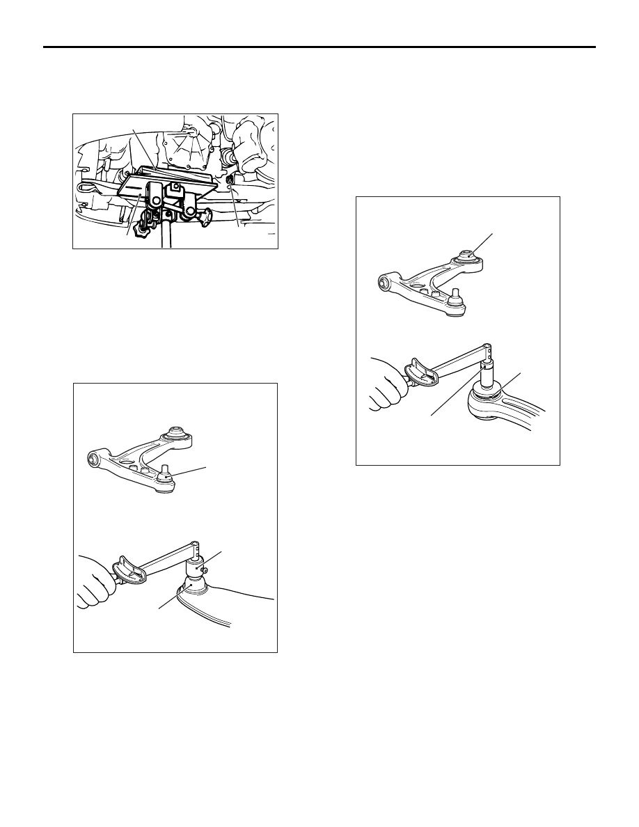
LOWER ARM BALL JOINT STARTING
TORQUE CHECK
AC504613AB
Ball joint
MB991006
Ball joint
1. After shaking the lower arm ball joint stud several
times, use special tool preload socket
(MB991006) to measure the starting torque of the
ball joint.
Standard value: 0.5
− 3.4 N⋅m
2. When the measured value exceeds the standard
value, replace the lower arm assembly.
3. When the measured value is lower than the
standard value, check that the lower arm ball joint
turns smoothly without excessive play. If there is
no excessive play, the ball joint can be reused.
PILLOW BALL BUSHING STARTING
TORQUE CHECK
AC504614AB
Pillow ball joint
Pillow ball
bushing
MB990326
1. Insert the bolt to the lower arm pillow ball bushing.
In the opposite direction, insert the washer then
install the nut. After rotating the inner sleeve
(contained washer) several times, measure the
starting torque of the lower arm pillow ball bushing
using special tool preload socket (MB990326).
Standard value: 0.5
− 3.0 N⋅m
2. When the measured value exceeds the standard
value, replace the pillow ball bushing.
3. When the measured value is lower than the
standard value, check that the lower arm pillow
ball bushing turns smoothly without excessive
play. If there is no excessive play, the pillow ball
bushing can be reused.

LOWER ARM
FRONT SUSPENSION
33-12
LOWER ARM BALL JOINT DUST COVER
CHECK
1. Check the dust cover for cracks or damage by
pushing it with your finger.
2. If the dust cover is cracked or damaged, replace
the lower arm.
NOTE: Cracks or damage to the dust cover may
cause damage to the ball joint. When it is dam-
aged during service work, replace the dust cover.
BALL JOINT DUST COVER
REPLACEMENT
M1332008200312
If the dust cover is damaged accidentally during
service work, replace the dust cover as follows:
1. Remove the dust cover.
2. Apply multipurpose grease to the lip and inside of
the dust cover.
AC006135 AB
MB990800
Dust cover
3. Using special tool ball joint remover and installer
(MB990800), press the dust cover until it contacts
the lower arm assembly.
4. Press the dust cover with your finger to check that
there are no cracks or damage in the dust cover.
LOWER ARM PILLOW BALL BUSHING
REPLACEMENT
M1332008100564
AC504566AB
Pillow ball
bushing
Replace the bushing as follows:
AC504563
MB990651
MB991576
Lower arm
assembly
MB991816
AB
1. Use following special tools to drive out the
bushing.
• Bar (MB990651)
• Base (MB991576)
•
AC504565
Marking
60˚
AB
Bushing remover & installer base (MB991816)
2. Set the bushing to the lower arm assembly so that
the bushing marking and the opening are as
shown in the illustration.
Нет комментариевНе стесняйтесь поделиться с нами вашим ценным мнением.
Текст