Mitsubishi Lancer Evolution IX. Manual — part 571
CROSSMEMBER BAR
FRONT SUSPENSION
33-17
STABILIZER LINK BALL JOINT TURNING
TORQUE CHECK
AC001129
MB990326
AB
1. After shaking the ball joint stud several times,
install the nut to the stud and use special tool
preload socket (MB990326) to measure the
turning torque of the ball joint.
Standard value: 1.7
− 3.2 N⋅m
2. When the measured value exceeds the standard
value, replace the stabilizer link.
3. When the measured value is lower than the
standard value, check that the ball joint turns
smoothly without excessive play. If so, it is
possible to re-use that ball joint.
STABILIZER LINK BALL JOINT DUST
COVER CHECK
1. Check the dust cover for cracks or damage by
pushing it with your finger.
2. If the dust cover is cracked or damaged, replace
the stabilizer link.
NOTE: Cracks or damage of the dust cover may
cause damage to the ball joint.
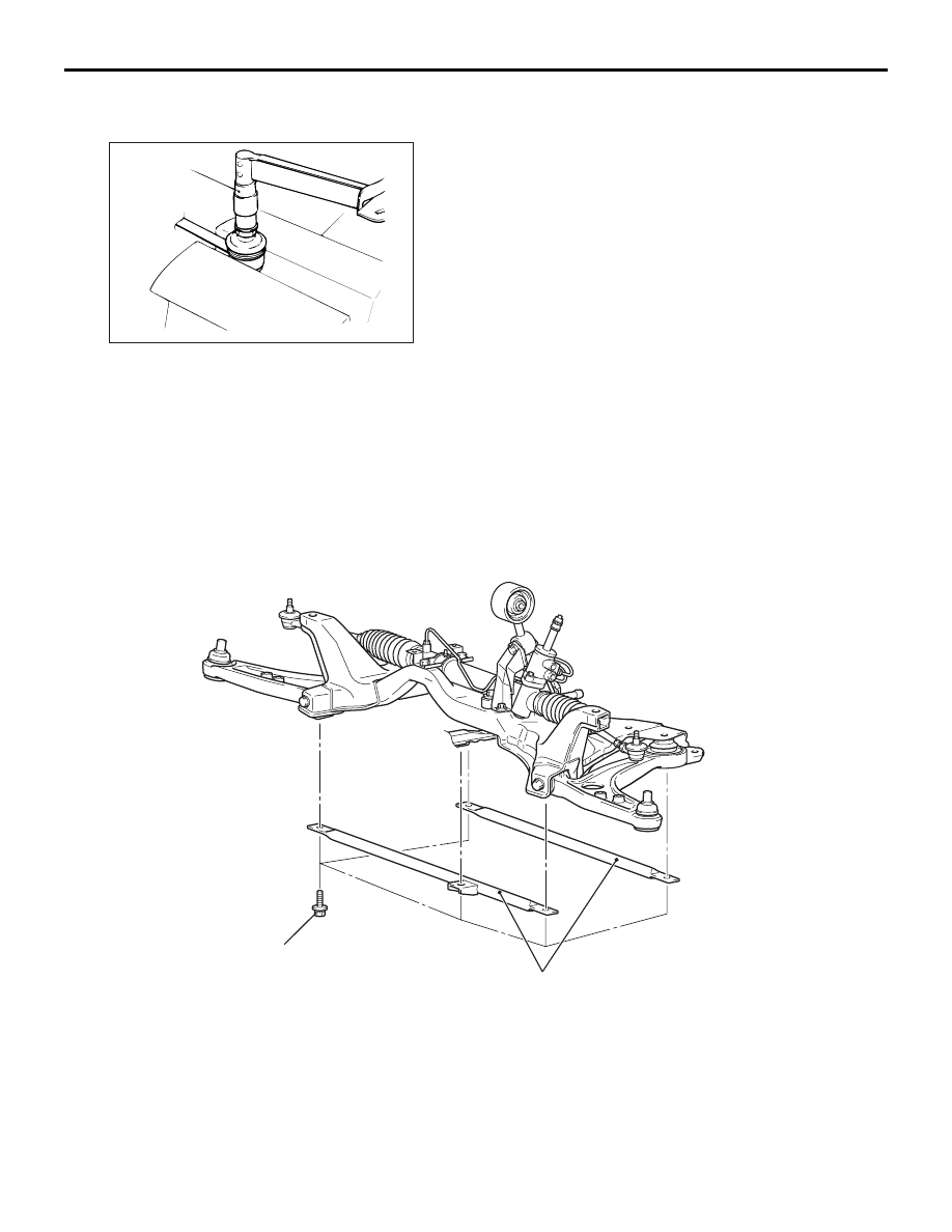
CROSSMEMBER BAR
REMOVAL AND INSTALLATION
M1332016100086
AC310742
Front axle crossmember bar
AB
49 ± 10 N·m
NOTES
34-1
GROUP 34
CONTENTS
GENERAL INFORMATION . . . . . . . .
SERVICE SPECIFICATIONS. . . . . . .
SPECIAL TOOLS. . . . . . . . . . . . . . . .
ON-VEHICLE SERVICE. . . . . . . . . . .
REAR WHEEL ALIGNMENT CHECK AND
ADJUSTMENT . . . . . . . . . . . . . . . . . . . . . .
BALL JOINT DUST COVER INSPECTION
REAR SUSPENSION ASSEMBLY . .
REMOVAL AND INSTALLATION . . . . . . . .
UPPER ARM ASSEMBLY . . . . . . . . .
REMOVAL AND INSTALLATION . . . . . . . .
INSPECTION . . . . . . . . . . . . . . . . . . . . . . .
UPPER ARM BALL JOINT DUST COVER
REPLACEMENT . . . . . . . . . . . . . . . . . . . . .
TRAILING ARM . . . . . . . . . . . . . . . . .
REMOVAL AND INSTALLATION . . . . . . . .
INSPECTION. . . . . . . . . . . . . . . . . . . . . . . .
TRAILING ARM BALL JOINT DUST COVER
REPLACEMENT . . . . . . . . . . . . . . . . . . . . .
LOWER ARM ASSEMBLY AND ASSIST
LINK . . . . . . . . . . . . . . . . . . . . . . . . . .
REMOVAL AND INSTALLATION . . . . . . . .
INSPECTION. . . . . . . . . . . . . . . . . . . . . . . .
ASSIST LINK BALL JOINT DUST COVER
REPLACEMENT . . . . . . . . . . . . . . . . . . . . .
SHOCK ABSORBER ASSEMBLY . . .
REMOVAL AND INSTALLATION . . . . . . . .
DISASSEMBLY AND ASSEMBLY . . . . . . .
STABILIZER BAR. . . . . . . . . . . . . . . .
REMOVAL AND INSTALLATION . . . . . . . .
INSPECTION. . . . . . . . . . . . . . . . . . . . . . . .
STABILIZER BAR LINK BALL JOINT DUST
COVER REPLACEMENT . . . . . . . . . . . . . .

GENERAL INFORMATION
REAR SUSPENSION
34-2
GENERAL INFORMATION
M1341000100706
A trailing arm type multi-link suspension is used for
the rear suspension. In contrast to the trailing arm
multi-link system used on the Lancer, the Lancer
Evolution uses a newly developed multi-link system
built on a double wishbone base to achieve superior
handling stability. Optimum design of the suspension
points and use of aluminium parts for the suspension
arms and crossmember reduces weight. In addition,
use of ball joints on the suspension arms reduce fric-
tion and creates a suspension system that exhibits
superior stroke characteristics that respond well
under all driving conditions.
CONSTRUCTION DIAGRAM
AC211385
AC
Shock absorber
Assist link
control bar
Coil spring
Crossmember
(forged aluminium)
Lower arm assembly
(forged aluminium)
Trailing arm assembly
(forged aluminium )
Upper arm assembly
(forged aluminium)
Differential support
member
Differential
support arm
Stabilizer bar
Assist link
(forged aluminium)
Stabilizer bar link
SPECIFICATION
COIL SPRING
Item
Standard
Option
Wire diameter mm
12
12
Average diameter mm
88
88
Free length mm
287
277
Нет комментариевНе стесняйтесь поделиться с нами вашим ценным мнением.
Текст