Mitsubishi Lancer Evolution IX. Manual — part 459
TROUBLESHOOTING
MULTIPORT FUEL INJECTION (MPI)
13A-311
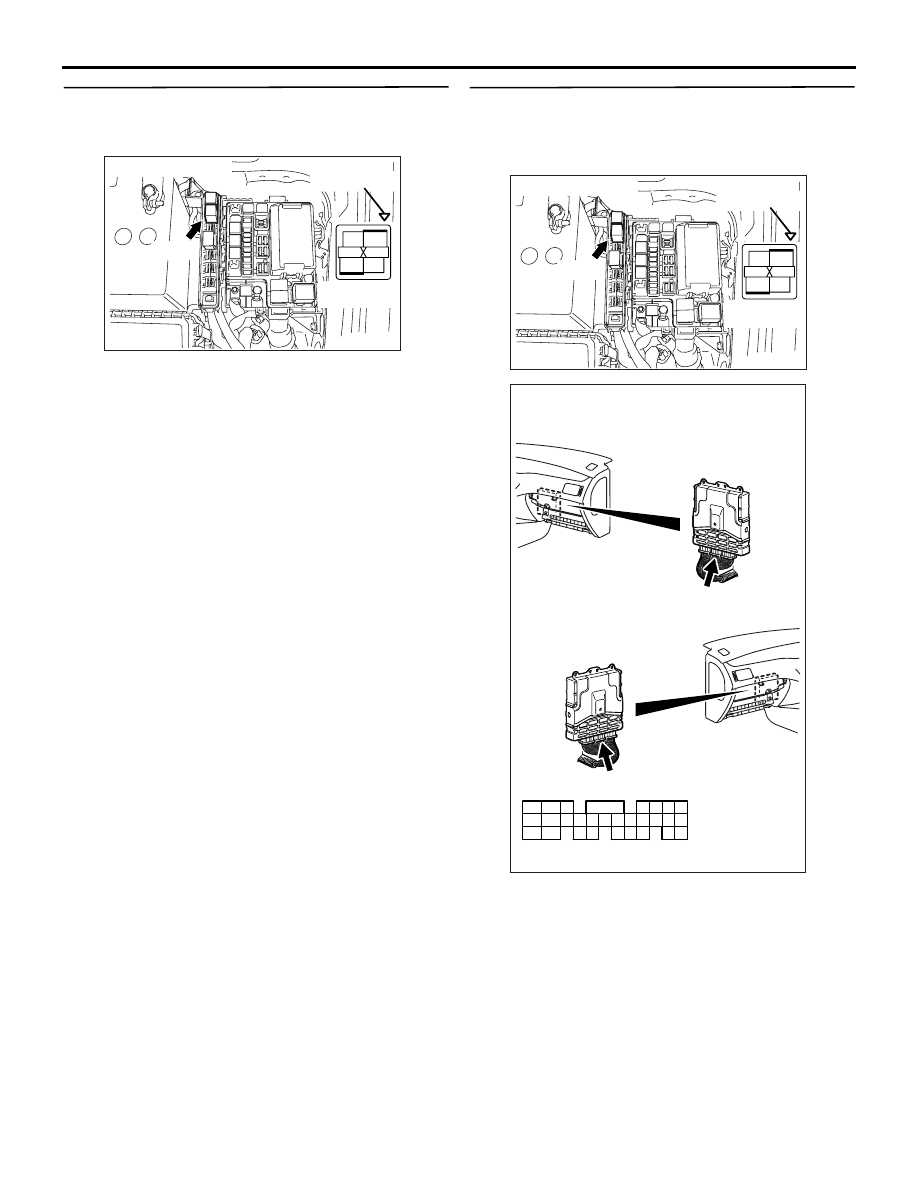
STEP 16. Check harness between B-12X
(terminal No. 1, No. 2) engine control relay
connector and battery.
NOTE: Before checking harness, check intermediate
connector A-13
*1
or C-31
*2
, and repair if necessary.
• Check power supply line for damage.
Q: Is the check result normal?
YES :
Go to Step 17 .
NO :
Repair the damaged harness wire.
STEP 17. Check harness between B-12X
(terminal No. 3) engine control relay connector
and C-119 (terminal No. 57) engine-ECU
connector.
• Check earthing line for damage.
Q: Is the check result normal?
YES :
Go to Step 18 .
NO :
Repair the damaged harness wire.
AK305003
2
1
3
4
AB
Connector : B-12X
B-12X
Harness side
connector
Relay box’s
triangle marks
AK305003
2
1
3
4
AB
Connector : B-12X
B-12X
Harness side
connector
Relay box’s
triangle marks
AK501994
65
43
50
42
49
41
48
60
61
64
46
47
58
59
67
68
45
56
66
52 51
44
53
62
54
63
57
55
AB
Connector: C-119
C-119 (GR)
C-119 (GR)
Harness side connector
<L. H. drive vehicles>
<R. H. drive vehicles>

TROUBLESHOOTING
MULTIPORT FUEL INJECTION (MPI)
13A-312
STEP 18. Check harness between B-12X
(terminal No. 4) engine control relay connector
and C-119 (terminal No. 47 and No. 59)
engine-ECU connector.
NOTE: Before checking harness, check intermediate
connector C-105, and repair if necessary.
• Check output line for damage.
Q: Is the check result normal?
YES :
Go to Step 19 .
NO :
Repair the damaged harness wire.
STEP 19. Check the trouble symptoms.
Q: Does trouble symptom persist?
YES :
Replace the engine-ECU.
NO :
Intermittent malfunction (Refer to GROUP
00
− How to Use
Troubleshooting/Inspection Service Points
).
AK305003
2
1
3
4
AB
Connector : B-12X
B-12X
Harness side
connector
Relay box’s
triangle marks
AK501994
65
43
50
42
49
41
48
60
61
64
46
47
58
59
67
68
45
56
66
52 51
44
53
62
54
63
57
55
AB
Connector: C-119
C-119 (GR)
C-119 (GR)
Harness side connector
<L. H. drive vehicles>
<R. H. drive vehicles>
TROUBLESHOOTING
MULTIPORT FUEL INJECTION (MPI)
13A-313
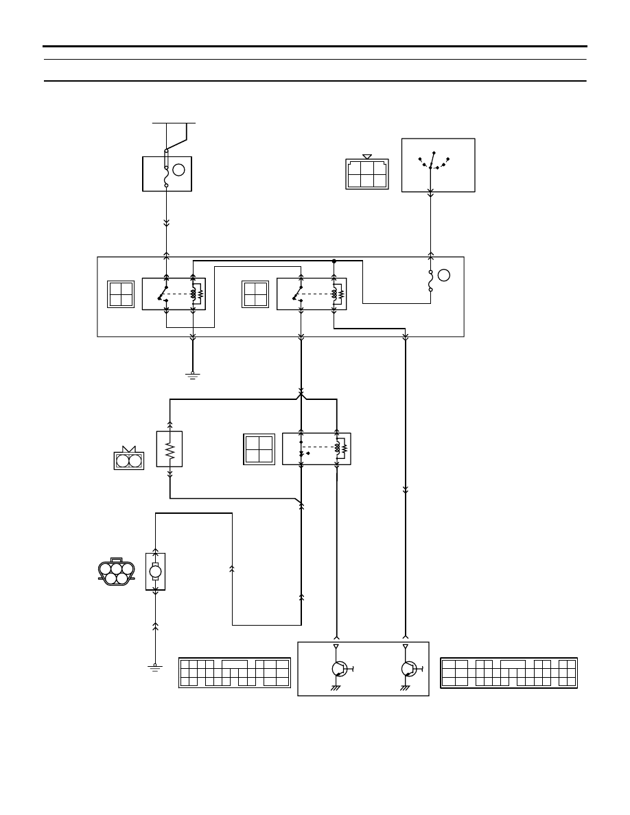
Inspection Procedure 24: Fuel Pump System
AK501829
1 2 3
4 5
3 4
1 2
3 4
1 2
1 2
1
2
3
4
1 2 3
4 5 6
M
65
43
50
42
49
41
48
60 61
64
46 47
58 59
67 68
45
56
66
52
51
44
53
62
54
63
57
55
2
3 4
5 6
7 8
9
11 12 13 14 15 16 17 18 19 20
30
21 22 23
24 25
26 27 28 29
3132 33
34 35
1
10
OFF
ON
OFF
ON
ON
OFF
15
7.5A
15A
J/B
Fuel pump
resistor
Fuel pump
relay (3)
Fuel pump
relay (1)
Fuel pump
relay (2)
Relay
box
Battery
Ignition
switch
Engine-ECU
Wire colour code
B: Black LG: Light green G: Green L: Blue W: White Y: Yellow SB: Sky blue BR: Brown O: Orange GR: Gray
R: Red P: Pink V: Violet PU: Purple
NOTE
*1: L.H. drive vehicles
*2: R.H. drive vehicles
AB
B
W
W
W
R
R
R-W
B
D-12
(MU802058)
B-121
MU802601
C-113 (*1)
or
C-112 (*2)
Fuel pump
and fuel
gauge unit
4
5
4
D-34
1
1
B-120
C-221
C-223
5
1
3
2
2
1
4
1
2
4
3
4
2
1
3
D-33
C-121
(MU803784)
R-B
V
V
R-W
R-W
W
W
W
B-W
GR
21
2
C-123
14
C-214
6
2
C-211
C-208
2
C-210
1 (*1) or 12 (*2)
C-129
13
1
C-214
11
C-214
55
IG2
ST
LOCK
ACC
IG1
R
Fuel pump circuit
8
C-119
(MU803782)
B
C-123
C-123
BR (*1)
or
B (*2)
TROUBLESHOOTING
MULTIPORT FUEL INJECTION (MPI)
13A-314
OPERATION
• The battery voltage is applied to the fuel pump
relay (1) (terminal No. 3) form the ignition switch.
• When the ignition switch is turned to the "ON"
position, the battery voltage is applied to the fuel
pump relay (2) (terminal No. 1) from the fuel
pump relay 1 (terminal No. 1).
• Battery voltage is applied to the fuel pump relay
(2) (terminal No. 3) from the ignition switch.
• During cranking and while the engine is running,
the engine-ECU turns ON the power transistor in
the engine-ECU in order to earth the coil of the
fuel pump relay (2). Consequently, the fuel pump
relay 2 turns ON, and the fuel pump relay (2) (ter-
minal No. 4) supplies the battery voltage to the
fuel pump and the fuel pump circuit resistor.
• While the engine operates with a low load, the
engine-ECU turns ON the power transistor in the
engine-ECU in order to earth the coil of the fuel
pump relay (3). Consequently, the fuel pump
relay (3) turns OFF, and the fuel pump resistor
(terminal No. 2) supplies the battery voltage to
the fuel pump (terminal No. 5).
• While the engine operates with a high load, the
engine-ECU turns OFF the power transistor in
the engine-ECU, causing the fuel pump relay (3)
to turn ON. Consequently, the fuel pump relay (3)
(terminal No. 1) supplies power directly to the fuel
pump (terminal No. 5).
FUNCTION
• The engine-ECU turns the fuel pump relay ON
during cranking and engine operation, and sup-
plies the drive power to the fuel pump.
• When operating with a low load, the engine-ECU
supplies power to the fuel pump via the resistor.
When operating with a high load, power is directly
supplied and the fuel pump fuel discharge
amount is increased.
PROBABLE CAUSES
• Failed fuel pump relay
• Failed fuel pump
• Failed fuel pump resistor
• Open/short circuit in fuel pump drive circuit or
loose connector contact
• Failed engine-ECU
DIAGNOSIS PROCEDURE
NOTE:
.
*1: L.H. drive vehicles
*2: R.H. drive vehicles
STEP 1. M.U.T.-II/III actuator test
• Refer to Actuator Test Reference Table
.
a. Item No. 07: Fuel pump
Q: Is the check result normal?
YES :
Go to Step 2 .
NO :
Go to Step 3 .
STEP 2. M.U.T.-II/III actuator test
• Refer to Actuator Test Reference Table
.
a. Item No. 13: Fuel pump 3
Q: Is the check result normal?
YES :
Intermittent malfunction (Refer to GROUP
00
− How to Use
Troubleshooting/Inspection Service Points
.)
NO :
Go to Step 18 .
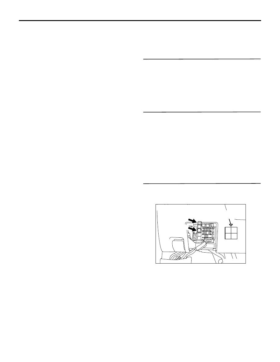
STEP 3. Connector check: C-223 fuel pump relay
(1) connector and C-221 fuel pump relay (2)
connector.
Q: Is the check result normal?
YES :
Go to Step 4 .
NO :
Repair or replace the connector.
AK305258
2 1
3
4
AB
C-221
C-223
Harness side
connector
Junction block’s
triangle marks
Connector: C-221, C-223
Нет комментариевНе стесняйтесь поделиться с нами вашим ценным мнением.
Текст